Table of Contents
Advertisement
Quick Links
EPCE-TB
Electric cylinder unit
Operating instructions
8151733
2021-02b
[8151735]
Translation of the original instructions
© 2021 all rights reserved to Festo SE & Co. KG
IO-Link® is a registered trademark of its respective trademark holder in certain
countries.
1
About this document
1.1
Applicable documents
All available documents for the product è www.festo.com/sp.
Type
Product
EMCS-ST
Integrated drive
NEFC-M12G8-0.3-M12G5-LK
Adapter
Tab. 1: Applicable documents for the product
1.2
Product version
This documentation refers to the following datasets:
– Firmware version of the integrated drive from "v19.0.4.107_release"
– IO-Link device description file (IODD) from V1.2.6
When using a different firmware version, check whether a corresponding version
of the documentation is available è www.festo.com/sp.
2
Safety
2.1
Safety instructions
– Observe labelling on the product.
– Prior to assembly, installation and maintenance work: Switch off power supply,
ensure that it is off and secure it against being switched back on.
– Store the product in a cool, dry, UV-protected and corrosion-protected environ-
ment. Ensure that storage times are kept to a minimum.
– Observe tightening torques. Unless otherwise specified, the tolerance
is ± 20 %.
2.2
Intended use
The electric cylinder unit EPCE-TB is intended for linear movement of payloads or
as a drive when external guides are used between two end positions.
2.3
Training of qualified personnel
Work on the product may only be carried out by qualified personnel who can
evaluate the work and detect dangers.
The qualified personnel have knowledge and experience in dealing with electric
drive systems.
3
Additional information
– Contact the regional Festo contact if you have technical problems
è www.festo.com.
– Accessories and spare parts è www.festo.com/catalogue.
4
Product overview
4.1
Scope of delivery
The following components are included in the scope of delivery:
– Electric cylinder unit EPCE-TB
– Instruction manual for the electric cylinder unit EPCE-TB
– Adapter for IO-Link operation (optional accessory)
è www.festo.com/catalogue
4.2
The electric cylinder unit converts the rotary motion of the mounted motor into
a linear motion of the piston rod. The torque of the motor is transmitted to the
piston rod via the toothed belt drive (TB). The linear movement of the piston rod is
guided by the guide in the blanking plate.
4.3
Festo SE & Co. KG
1
Ruiter Straße 82
73734 Esslingen
2
Deutschland
+49 711 347-0
3
www.festo.com
4
5
6
Fig. 1: System overview EPCE-TB
Items 1 ... 5 are not included in the scope of delivery.
4.3.1
1
Table of contents
Manual
Assembly instructions
Fig. 2: Product design EPCE-TB
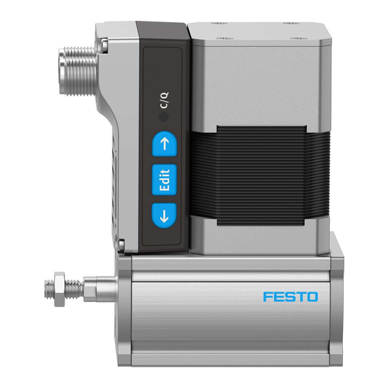
Electrical connections, display and operating components (HMI)
1
Fig. 3: Electrical connections, display
5
NOTICE
Unexpected and unbraked movement of components
• Secure moving components for transport.
Transport and Storage Conditions
– Store and transport the product in its original packaging.
– Store product in a cool, dry, shaded and corrosion protected environment.
– Store product in ambient conditions without oils, greases and degreasing
vapours.
– Ensure short storage times.
6
Function
System overview
Product design
2
3
4
5
6
7
8
(example EPCE-...-MF)
2
3
4
5
6
7
8
and operating components
(HMI)
Transport
Assembly
PELV fixed power supply for load
1
voltage
PELV fixed power supply for logic
2
voltage
3
Application software
4
PC or laptop
Controller or IO-Link master
5
6
Electric cylinder unit EPCE-TB
1
Electric cylinder unit EPCE-TB
Controller housing
2
3
Warning symbol "Attention! Hot
surface"
4
Integrated drive EMCS-ST
Product labelling
5
6
Slot for profile mounting
Through-hole for direct fastening
7
8
Thread and centre hole for direct
fastening
1
LED display menu (Speed Out, ...,
Demo)
LED parameter display
2
3
LED C/Q
4
Connection for load voltage
[Power]
Logic voltage connection and dig-
5
ital I/O or IO-Link connections
[Logic]
Pushbutton actuator (right arrow)
6
7
Pushbutton actuator (Edit)
8
Pushbutton actuator (left arrow)
Advertisement
Table of Contents

Related Manuals for Festo EPCE-TB


Summary of Contents for Festo EPCE-TB
- Page 1 [Logic] Pushbutton actuator (right arrow) Intended use The electric cylinder unit EPCE-TB is intended for linear movement of payloads or Pushbutton actuator (Edit) as a drive when external guides are used between two end positions. Fig. 3: Electrical connections, display...
-
Page 2: Installation
2. Place the mounting attachments on the support points. Observe maximum tightening torque. The piston rod must not be turned. 3. Tighten retaining screws. Observe max. tightening torque and max. screw-in depth. For additional information, contact your local Festo Service. Profile mounting Direct fastening EAHF-L2... - Page 3 An input current at pin 1 (L+) of 100 ... 150 mA is required for operation. • Update parameter set • Data backup (Data Storage) è "Integrated drive EMCS" instruction manual è www.festo.com/sp Commissioning: DIO operation (digital I/Os) Preparation: 1. Check the mounting of the drive system.
-
Page 4: Operation
Tab. 10: Initialise restart sequence with reference end position "Ref" Tab. 8: Dimension reference system for linear drive systems Reference end positions Ref with EPCE-TB The following table shows the default position of the reference end positions Ref as a function of the piston rod variants FL/BL/FR/BR. -
Page 5: Point-To-Point Operation
If automatic storage is activated (0x0109.0 = true, default), parameter changes in the device data (= data storage parameters è "Integrated drive EMCS" instruction manual è www.festo.com/sp) are made automatically and perma- nently saved in the flash memory. Exceeding the maximum permissible 100,000 write cycles results in irreparable damage to the flash memory and the device, e.g. -
Page 6: Maintenance
Warning Warnings 0x... yellow light Error Common device error or … 0x1000 unlisted errors Remedy red light – Contact Festo 0x000F t monitoring output stage 0x1805 (15) error limit Remedy – 0x0016 Undervoltage in logic supply 0x1804 (22) 1) 10, 20, ..., 100% of maximum value... - Page 7 Tab. 15: Overview of fault clearance 11.2 Repair Repair or maintenance of the product is not permissible. – Replace with an identical product è www.festo.com/spareparts. Replacement 1. Save the application parameters to the IO-Link master è "Integrated drive EMCS" instruction manual è www.festo.com/sp.
- Page 8 Characteristic curves Additional information è www.festo.com/catalogue. Transverse load on piston rod EPCE-TB Max. transverse load Fy, Fz on the piston rod as a function of the piston rod length Fig. 10: Max. transverse load Fy, Fz and piston rod length l Fig.
Need help?
Do you have a question about the EPCE-TB and is the answer not in the manual?
Questions and answers