
Related Manuals for Hy-Brid Lifts 1 Series


Summary of Contents for Hy-Brid Lifts 1 Series
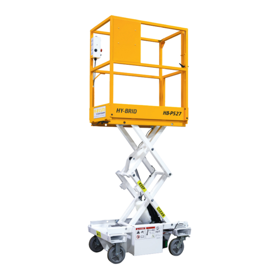
- Page 1 BY CU STO M EQUIPMENT LLC MAINTENANCE & TROUBLESHOOTING MANUAL SUPO-643 REV A PUSH-AROUND AERIAL WORK PLATFORM HB-P527 SERIES I...
-
Page 2: Notes
The purpose of this Maintenance Manual is to provide qualifi ed service personnel with information for servicing and maintaining Hy-Brid Lifts. All information in this manual must be read and understood before any attempt is made to service this machine. -
Page 3: Table Of Contents
TABLE OF CONTENTS INDEX OF FIGURES NOTES ......................................2 FIGURE 1: Maintenance Lock Use ................................ 7 FIGURE 2: Maintenance Lock Storage ..............................7 FOREWORD ....................................3 FIGURE 3: Battery Charger LED Display .............................. 9 TABLE OF CONTENTS ................................4 FIGURE 4: Platform Control Removal..............................10 INDEX OF FIGURES .................................. -
Page 4: Section 1 | Safety
SECTION 1 | SAFETY SECTION 1 | SAFETY 1.3 | SAFETY GUIDELINES 1.1 | SAFETY SYMBOLS Maintenance Lock The maintenance lock must be placed into position whenever the machine is being serviced in the raised or partially DANGER raised position. Serious injury and/or death could result if maintenance lock is not used properly. “DANGER”... -
Page 5: Section 2 | Maintenance
SECTION 2 | MAINTENANCE SECTION 2 | MAINTENANCE 2.1 | BATTERY MAINTENANCE Do not operate unit while charging. Shortened battery life will result. To Charge: Battery cycle life will vary significantly depending on the depth of discharge. The deeper the depth of discharge the •... -
Page 6: Removing Platform Control
SECTION 3 | MAINTENANCE CHECKLISTS SECTION 2 | MAINTENANCE 2.4 | REMOVING PLATFORM CONTROL For maintenance, the upper control panel will need to be unscrewed and removed in order to operate from ground level. Elevate the platform to set the mainenance lock in place. FAILURE TO PERFORM INSPECTIONS AND PREVENTATIVE MAINTENANCE AT RECOMMENDED INTERVALS MAY RESULT IN THE UNIT BEING OPERATED WITH A DEFECT THAT MAY... -
Page 7: Pre-Start Inspection Checklist
SECTION 3 | MAINTENANCE CHECKLISTS SECTION 3 | MAINTENANCE CHECKLISTS 3.1 | PRE-START INSPECTION CHECKLIST 3.2 | FREQUENT INSPECTION CHECKLIST AERIAL PLATFORMS SHALL BE INSPECTED, SERVICED, AND ADJUSTED TO THIS CHECKLIST MUST BE USED AT THE BEGINNING OF EACH SHIFT OR MANUFACTURER’S REQUIREMENTS BY A QUALIFIED MECHANIC PRIOR TO AFTER EVERY SIX TO EIGHT HOURS OF USE. -
Page 8: Frequent Inspection Checklist
SECTION 3 | MAINTENANCE CHECKLISTS 3.3 | FREQUENT INSPECTION CHECKLIST AERIAL PLATFORMS SHALL BE INSPECTED, SERVICED, AND ADJUSTED TO MANUFACTURER’S REQUIREMENTS BY A QUALIFIED MECHANIC PRIOR TO EACH SALE, LEASE, OR RENTAL, AND EVERY 3 MONTHS OR 150 HOURS, WHICHEVER COMES FIRST. Model Number: Serial Number: •... -
Page 9: Section 4 | Technical References
SECTION 4 | TECHNICAL REFERENCES SECTION 4 | TECHNICAL REFERENCES 4.1 | HYDRAULIC SCHEMATIC Part No HS-HB-P3.6/527 MAINTENANCE & TROUBLESHOOTING SUPO-643 MAINTENANCE & TROUBLESHOOTING SUPO-643 HB-P527 REV A HB-P527 REV A... -
Page 10: Electrical Schematic
SECTION 4 | TECHNICAL REFERENCES SECTION 4 | TECHNICAL REFERENCES 4.2 | ELECTRICAL SCHEMATIC Part No WS-143-20-001-50 MAINTENANCE & TROUBLESHOOTING SUPO-643 MAINTENANCE & TROUBLESHOOTING SUPO-643 HB-P527 REV A HB-P527 REV A... -
Page 11: Section 5 | Wiring Diagrams
SECTION 5 | WIRING DIAGRAMS SECTION 5 | WIRING DIAGRAMS 5.1 | WIRING DIAGRAM Part No WD-143-20-001-50 MAINTENANCE & TROUBLESHOOTING SUPO-643 MAINTENANCE & TROUBLESHOOTING SUPO-643 HB-P527 REV A HB-P527 REV A... -
Page 12: Upper Control Wiring Diagram
SECTION 5 | WIRING DIAGRAMS SECTION 5 | WIRING DIAGRAMS 5.2 | UPPER CONTROL WIRING DIAGRAM Part No WD-143-21-004-50 MAINTENANCE & TROUBLESHOOTING SUPO-643 MAINTENANCE & TROUBLESHOOTING SUPO-643 HB-P527 REV A HB-P527 REV A... -
Page 13: Section 6 | Trouble Shooting Flowcharts
SECTION 6 | TROUBLE SHOOTING FLOWCHARTS SECTION 6 | TROUBLE SHOOTING FLOWCHARTS 6.1 | TROUBLESHOOTING FLOWCHART: POWER Troubleshooting Step 1: Main Power MAINTENANCE & TROUBLESHOOTING SUPO-643 MAINTENANCE & TROUBLESHOOTING SUPO-643 HB-P527 REV A HB-P527 REV A... -
Page 14: Troubleshooting Flowchart: Elevating
SECTION 6 | TROUBLE SHOOTING FLOWCHARTS SECTION 6 | TROUBLE SHOOTING FLOWCHARTS 6.2 | TROUBLESHOOTING FLOWCHART: ELEVATING Troubleshooting Step 2A: Elevating MAINTENANCE & TROUBLESHOOTING SUPO-643 MAINTENANCE & TROUBLESHOOTING SUPO-643 HB-P527 REV A HB-P527 REV A... -
Page 15: Troubleshooting Flowchart: Lowering
SECTION 6 | TROUBLE SHOOTING FLOWCHARTS SECTION 6 | TROUBLE SHOOTING FLOWCHARTS 6.3 | TROUBLESHOOTING FLOWCHART: LOWERING Troubleshooting Step 2B: Lowering MAINTENANCE & TROUBLESHOOTING SUPO-643 MAINTENANCE & TROUBLESHOOTING SUPO-643 HB-P527 REV A HB-P527 REV A... -
Page 16: Section 7 | Parts Diagrams
SECTION 7 | PARTS DIAGRAMS SECTION 7 | PARTS DIAGRAMS 7.2 | MAIN POWER/SAFETY CIRCUIT USE ONLY MANUFACTURER APPROVED REPLACEMENT PARTS. USE OF NON-OEM PARTS WILL VOID WARRANTY. REPLACEMENT OF THE FOLLOWING COMPONENTS WILL AFFECT THE STRENGTH, STABILITY, OR SAFETY FUNCTION OF THE UNIT: BATTERY, HYDRAULIC CYLINDER, AND ALL STRUCTURAL COMPONENTS. -
Page 17: Elevate/Lower Circuit Parts
SECTION 7 | PARTS DIAGRAMS SECTION 7 | PARTS DIAGRAMS 7.3 | ELEVATE/LOWER CIRCUIT PARTS Item # Part Number Description HYDR-002 Hydraulic Pump HYDR-019 Hydraulic Fitting HYDR-022-3 Low Pressure Hydraulic Line HYDR-681 Hydraulic Grommet Hydraulic Fluid: Not available as a replacement part. Replace with Flomite HYDR-032 #150, Dexron II, Mobil-DTE 2, or equivalent. -
Page 18: Wheels/Breaks
SECTION 7 | PARTS DIAGRAMS SECTION 7 | PARTS DIAGRAMS 7.4 | WHEELS/BREAKS 7.5 | COVERS/OTHER Item # Part Number Description 143-21-008-50-K Rigid Caster Assembly 143-21-009-50-K Swivel Caster Assembly WHEE-706-KIT Wheel 20.32 cm (8”) Item # Part Number Description WHEE-002-1 Bearing Kit 1000307601 RAIL,GATE LATCH... -
Page 19: Section 8 | Warranty
SECTION 8 | WARRANTY SECTION 8 | WARRANTY Limited warranty Notwithstanding anything in this limited warranty to the contrary, the company shall not be obligated to replace the entire product if a covered defect can be remedied by the repair or replacement of a defective part, WARRANTY STATEMENT—NORTH AMERICA ONLY component or assembly. -
Page 20: Notes
NOTES NOTES MAINTENANCE & TROUBLESHOOTING SUPO-643 MAINTENANCE & TROUBLESHOOTING SUPO-643 HB-P527 REV A HB-P527 REV A... - Page 21 © 2015 Custom Equipment, LLC 2647 Highway 175 Richfield, WI 53076 U.S.A. Tel.: +1-262-644-1300 Fax: +1-262-644-1320 www.hybridlifts.com Service@Customequipmentlifts.com “Hy-Brid Lifts” is a trademark of Custom Equipment, LLC. These machines comply with specified ANSI & CSA requirements Revision Date: September 2015 Printed In The USA...
Need help?
Do you have a question about the 1 Series and is the answer not in the manual?
Questions and answers