Sign In
Upload
Download
Table of Contents
Contents
Add to my manuals
Delete from my manuals
Share
URL of this page:
HTML Link:
Bookmark this page
Add
Manual will be automatically added to "My Manuals"
Print this page
×
Bookmark added
×
Added to my manuals
Manuals
Brands
ZKTeco Manuals
Automatic Barriers
SBTL2000
Instructions manual
ZKTeco SBTL2000 Instructions Manual
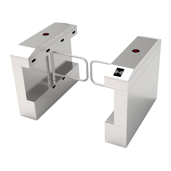
Swing barrier
Hide thumbs
1
Table Of Contents
2
3
4
5
6
7
8
9
10
11
12
13
14
15
16
17
page
of
17
Go
/
17
Contents
Table of Contents
Bookmarks
Table of Contents
Table of Contents
Chapter 1 Product Introduction
Model Number and Access Control
Chassis and Dimensions
Mechanical System of the Swing Barrier
Electronic Control System
The Working Principle of Swing Barrier
System Composition of the Product
Chapter 2 The Installation of the Product
Installation Notes
Installation Position of the Swing Barrier
Cables Installation and Fixation
Chapter 3 Menu Operation
Function Introduction
Menu Introduction
Chapter 4 Common Failure Analysis
Chapter 5 Product Maintenance
Chassis Maintenance
Movement Maintenance
Power Maintenance
Advertisement
Quick Links
Download this manual
Swing Barrier Instructions
Applicable Models: SBTL 2000 / 3000
Date: Mar. 2021
Version: 1.0
pplicable Models: SBTL 2000 / 3000
Table of
Contents
Previous
Page
Next
Page
1
2
3
4
5
Advertisement
Table of Contents
Need help?
Do you have a question about the SBTL2000 and is the answer not in the manual?
Ask a question
Questions and answers
Related Manuals for ZKTeco SBTL2000
Automatic Barriers ZKTeco SBTL300 Series User Manual
Swing barrier (16 pages)
Automatic Barriers ZKTeco SBTL3000 Instructions Manual
Swing barrier (17 pages)
Automatic Barriers ZKTeco ProEntrance Series Installation Manual
Swing barrier (8 pages)
Automatic Barriers ZKTeco BG500 Series User Manual
Barrier gate (27 pages)
Automatic Barriers ZKTeco BGM1000 Series User Manual
Barrier gate (app version) (32 pages)
Automatic Barriers ZKTeco CMP-200 Series User Manual
(24 pages)
Automatic Barriers ZKTeco BGM2000 Series User Manual
Barrier gate app version (32 pages)
Automatic Barriers ZKTeco BG1000 Series User Manual
Barrier gate (35 pages)
Automatic Barriers ZKTeco CMP-200 User Manual
(15 pages)
Automatic Barriers ZKTeco CMP-300 User Manual
(25 pages)
Automatic Barriers ZKTeco ProBG3000 Series User Manual
Barrier gate (30 pages)
Automatic Barriers ZKTeco Mars-S100 Series User Manual
(41 pages)
Automatic Barriers ZKTeco PB3000 Installation Manual
(7 pages)
Automatic Barriers ZKTeco Mars Pro-S1000 Series Installation Manual
(16 pages)
Automatic Barriers ZKTeco LB330 User Manual
(21 pages)
Automatic Barriers ZKTeco FBL200 User Manual
Flap barrier (20 pages)
This manual is also suitable for:
Sbtl2011
Sbtl2022
Sbtl3000
Sbtl3011
Sbtl3022
Table of Contents
Print
Rename the bookmark
Delete bookmark?
Delete from my manuals?
Login
Sign In
OR
Sign in with Facebook
Sign in with Google
Upload manual
Upload from disk
Upload from URL


Need help?
Do you have a question about the SBTL2000 and is the answer not in the manual?
Questions and answers