Table of Contents
Advertisement
Quick Links
OPERATING MANUAL ADT1
Keller AG für Druckmesstechnik
St. Gallerstrasse 119 | CH-8404 Winterthur
+41 52 235 25 25
info@keller-druck.ch
KELLER Ges. für Druckmesstechnik mbH
Schwarzwaldstrasse 17 | DE-79798 Jestetten
+49 7745 9214 0
eurocenter@keller-druck.ch
www.keller-druck.com
Version 08/2020
Änderungen vorbehalten
Unternehmen zertifiziert nach ISO9001
www.keller-druck.ch
Advertisement
Table of Contents

Related Manuals for Keller ADT1


Summary of Contents for Keller ADT1
- Page 1 OPERATING MANUAL ADT1 Keller AG für Druckmesstechnik KELLER Ges. für Druckmesstechnik mbH Version 08/2020 St. Gallerstrasse 119 | CH-8404 Winterthur Schwarzwaldstrasse 17 | DE-79798 Jestetten Änderungen vorbehalten +49 7745 9214 0 +41 52 235 25 25 Unternehmen zertifiziert nach ISO9001 www.keller-druck.ch...
-
Page 2: Table Of Contents
ADT1 ..................................4 Overview ................................... 4 1.1.1 Box: ................................4 1.1.2 Tube: ................................4 General Description / ADT1 Communication ......................5 Pre-Configuration ..............................5 Data Transmission / Technologie ..........................5 KOLIBRI Cloud ................................5 Hardware ................................6 ADT1 Tube................................. 6 ADT1 Box ................................... - Page 3 Device Registration .............................. 21 Integration with the Things Network (TTN) ......................21 ADT1 order information ............................22 Variants and options ............................... 22 Accessories................................22 Version History ..............................24 Version 08/2020 Seite 3 von 24...
-
Page 4: Adt1
This device can be linked with digital level sensors and pressure transmitters with the KELLER “D” and “X” low voltage With its wide range of water level sensors and pressure transmitters, KELLER can offer the right product lines. -
Page 5: General Description / Adt1 Communication
The range of communication is around 2km in dense urban area, up to 15km in the rural areas and is influenced by the position of the ADT1 and of the gateway, if the gateway is mounted in an high place the cover will be major than if is mounted in a low place. -
Page 6: Hardware
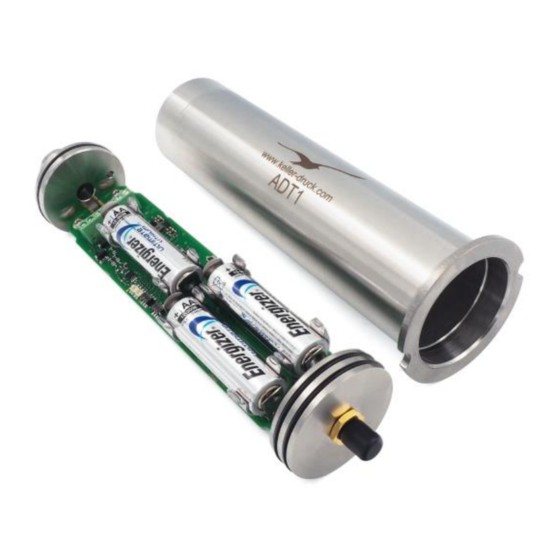
ADT1 Tube At just 43 mm in diameter, the cylindrical design of the ADT1 can simply be placed into the top of a two-inch-wide sounding tube standard in the groundwater measuring industry. It can be installed in a matter of seconds. The housing is designed to withstand condensation and temporary flooding. -
Page 7: How To Open And To Close The Housing
To close the unit, push with two fingers against the top of the housing/piston until it stops. Be sure that that the piston is completely inserted. Keep dry before opening and closing. To close the ADT1 Box you just squeeze the screws to- gether and make a quarter turn. -
Page 8: Connecting The Antenna
The cable gland is required to connect a level sensor. Feed the sensor cable through the cable gland and connect the cable ends to the corresponding terminal strip. The ADT1 tube has a nut with the wrench width 15 to provide a counter torque. -
Page 9: Locking Unit (Tube Only)
Locking unit (Tube only) The locking unit for the ADT1 Tube with antenna cover is available in size from 2 up to 6 inches. The sealed antenna can be covered by a lockable protective cap made of robust plastic. This protects the data logger against theft and damage by people or wild animals when level measurements are being taken in the open countryside. -
Page 10: Connection Terminal For The Sensors
Connection Terminal for the Sensors The ADT1 offers the possibility to connect a low cost I C, or a more precise RS485 Sensor of KELLER. The pin assignment of the ADT1 is shown as follow: 3.9.1 Connection for X-Line (RS485-Interface) “low voltage” type only Connect the black wire to the +3.5V supply voltage and... -
Page 11: Operating Modes
After a random delay of 0 … 6 seconds, the ADT1 sends the measurements. If the device has not joined the LoRaWAN® network yet, it will try to join until it succeeds (maximum 3 attempts per transmission). Afterwards, it will transmit the data. -
Page 12: Battery Lifetime Estimation
Battery lifetime estimation The value displayed in the “ADT1 Configuration” and the “KOLIBRI Cloud“ is the battery capacity calculated by the ADT1 as a percentage of remaining capacity. It is recommendable to change the battery if the value is less than 20%. Once the battery has been changed the value is once again shown as 99%. -
Page 13: Record Data Storage
All measured values are stored in the ADT1’s EEPROM. The memory is organized as a circular memory. This means that always the latest data is available whilst the oldest data is overwritten. -
Page 14: Configuration
Press button to save all settings to a configuration file Checkbox “Set ADT1 time to PC time at Enable checkbox -> The ADT1 clock will automatically be synchronized with PC clock if you write configuration” press the “Write Configuration Button” -> see number 4... -
Page 15: Settings
(temperature over bridge pressure gauge 1) TOB2 Temp. sensor of pressure sensor 2 [temperature / °C] P Baro Barometric pressure (ADT1) [pressure / bar] T Baro Air temperature (ADT1)[temperature / °C] P1 (X) Pressure (or Level) sensor with BUS Address (X) Hardware Settings Select connected sensor types. -
Page 16: Alarm
6.1.4 Alarm Number Description Explanation / Function Next Action Shows the date and time when the measurement task takes place and the alarm condition will be checked Interval Enter the time interval of the measuring and checking of the alarm condition... -
Page 17: Info
6.1.5 Info Number Description Explanation / Function Next Action Shows the date and time when the next info message will be sent Interval Shows the info message interval 6.1.6 Location info and Water level configuration Number Description Explanation / Function Position Assigns the coordinates (longitude, latitude, altitude) to a measuring location. -
Page 18: Error / Status & Debug
6.1.7 Error / Status & Debug Number Description Explanation / Function Modul Status Shows the status of the LoRa radio device. Battery Capacity / Voltage The calculated battery capacity and the measured battery voltage will be shown Send Info LoRa By pressing this button, the info message (contains battery voltage, capacity, humidity etc.) is... -
Page 19: Lorawan Settings
6.1.8 LoRaWAN Settings The parameters required for transmission can be changed in the LoRa settings. Number Description Explanation / Function Activation Method LoRaWAN offers two methods of device activation: OTAA (Over The Air) and ABP (Activation by Personalization). OTAA is the preferred method to join any LoRaWAN network. Depending on the activation method selected, the input fields are activated. -
Page 20: Activation
Adaptive Data Rate (ADR) is a mechanism for optimizing data rates, airtime and energy consumption in the network. ADR should be enabled for static devices, like the ADT1. To determine the optimal data rate, the network needs some measurements (uplink messages). The network calculate the so-called “margin”, which is used to determine how much the network can increase the data rate or lower the... -
Page 21: Device Registration
“The Things Network“. TTN is a contributor member of the LoRa Alliance and provide a set of open tools and a global, open network to connect things. This means the ADT1 is ready to use without any configuration changes. Nevertheless the ADT1 can be easily reconfigured through the USB interface to other network servers like Actility, Loriot etc. -
Page 22: Adt1 Order Information
ADT1 order information Variants and options Description Product number Picture ADT1-Tube-LR093 ADT1 Tube 320060.0004 Stub antenna, cable gland preinstalled ADT1-Box-LR093 ADT1 Box 320060.0002 Stub antenna, cable gland preinstalled Accessories Description Product number Picture Locking Unit 2’’ 509210.0001 3’’ 509210.0002 4’’... - Page 23 331005.0005 Antenna 320020.0110 Antenna for manhole cover with SMA connection Cable length: 2m 508620.0022 O-Ring 37x1.5 mm (Antenna side) 508620.0023 O-Ring 35x1.5 mm (cable gland side) 702505.0007 Silicagel bag, 5 g Version 08/2020 Seite 23 von 24...
-
Page 24: Version History
Version History Version Date Description 08/2020 07.08.2020 New document Version 08/2020 Seite 24 von 24...
Need help?
Do you have a question about the ADT1 and is the answer not in the manual?
Questions and answers