Table of Contents
Advertisement
Quick Links
Keller AG für Druckmesstechnik
St. Gallerstrasse 119 | CH-8404 Winterthur
+41 52 235 25 25
info@keller-druck.ch
OPERATING MANUAL
ADT1-LR
KELLER Ges. für Druckmesstechnik mbH
Schwarzwaldstrasse 17 | DE-79798 Jestetten
+49 7745 9214 0
eurocenter@keller-druck.ch
www.keller-druck.com
Version 05/2021
Änderungen vorbehalten
Unternehmen zertifiziert nach ISO9001
www.keller-druck.ch
Advertisement
Table of Contents

Subscribe to Our Youtube Channel
Related Manuals for Keller ADT1-LR


Summary of Contents for Keller ADT1-LR
- Page 1 OPERATING MANUAL ADT1-LR Keller AG für Druckmesstechnik KELLER Ges. für Druckmesstechnik mbH Version 05/2021 St. Gallerstrasse 119 | CH-8404 Winterthur Schwarzwaldstrasse 17 | DE-79798 Jestetten Änderungen vorbehalten +49 7745 9214 0 +41 52 235 25 25 Unternehmen zertifiziert nach ISO9001 www.keller-druck.ch...
-
Page 2: Table Of Contents
Contents ADT1 ..................................4 Overview ................................... 4 1.1.1 Box: ................................4 1.1.2 Tube: ................................4 General Description / ADT1 Communication ......................5 Pre-Configuration ..............................5 Data Transmission / Technologie ..........................5 KOLIBRI Cloud ................................5 Hardware ................................6 ADT1 Tube................................. 6 ADT1 Box ................................... - Page 3 6.1.10.4 LoRaWAN Adaptive Data Rate ......................21 Device Registration .............................. 22 Integration with the Things Network (TTN) ......................22 Perform water level configuration with ADT1 devices ..................23 Description ................................23 Basics for level measurement with pressure sensors ..................... 23 Air pressure dependence ............................
-
Page 4: Adt1
This device can be linked with digital level sensors and pressure transmitters with the KELLER “D” and “X” low voltage With its wide range of water level sensors and pressure transmitters, KELLER can offer the right product lines. -
Page 5: General Description / Adt1 Communication
KOLIBRI Cloud The KOLIBRI Cloud from KELLER offers simple and convenient access to your measurement data with your own personal login and SSL encryption. You can enjoy readily available data without the need to set up and maintain a database. The measurements can be displayed as graphs in no time at all and the export function allows you to download your data as Excel or CSV files. -
Page 6: Hardware
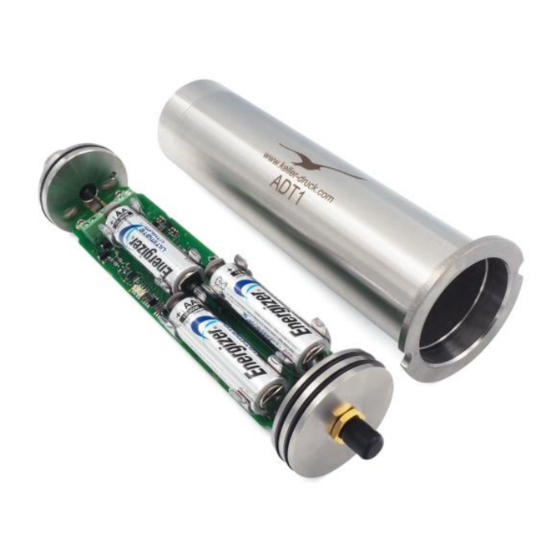
Hardware ADT1 Tube At just 43 mm in diameter, the cylindrical design of the ADT1 can simply be placed into the top of a two-inch-wide sounding tube standard in the groundwater measuring industry. It can be installed in a matter of seconds. The housing is designed to withstand condensation and temporary flooding. -
Page 7: How To Open And To Close The Housing
How to open and to close the housing To open the ADT1 Tube housing, push at the marked positions against the bottom of the housing/piston (see illustration below). The ADT1 Box can be easily opened with a Screwdriver PZ1, unscrew the four screws and carfully open the lid. -
Page 8: Connecting The Antenna
Connecting the antenna Screw the stub antenna into the corresponding SMA plug located at the top of the ADT1 and tighten by hand only. Make sure it is tight enough. CAUTION: Please only use the original accessories to prevent injuries and health risks. The Monopole antenna may have an ampli- fication of maximum 1.04dBi in the relevant frequency range. -
Page 9: Locking Unit (Tube Only)
Locking unit (Tube only) The locking unit for the ADT1 Tube with antenna cover is available in size from 2 up to 6 inches. The sealed antenna can be covered by a lockable protective cap made of robust plastic. This protects the data logger against theft and damage by people or wild animals when level measurements are being taken in the open countryside. -
Page 10: Connection Terminal For The Sensors
Connection Terminal for the Sensors The ADT1 offers the possibility to connect a low cost I C, or a more precise RS485 Sensor of KELLER. The pin assignment of the ADT1 is shown as follow: 3.9.1 Connection for X-Line (RS485-Interface) “low voltage” type only Connect the black wire to the +3.5V supply voltage and... -
Page 11: Operating Modes
ADT1 Measurement Cycle (Active Mode) During the active mode, the device periodically reads the values of the connected KELLER sensor with sampling period = 30 minutes (default, configurable) and stores the data in the internal EEPROM (RECORD). Therefore, the ADT1 supplies the pressure transmitter and reads the user-selected channels, when the values have been read out the power supply is switched off again. -
Page 12: Battery Lifetime Estimation
Battery lifetime estimation The value displayed in the “ADT1 Configuration” and the “KOLIBRI Cloud“ is the battery capacity calculated by the ADT1 as a percentage of remaining capacity. It is recommendable to change the battery if the value is less than 20%. Once the battery has been changed the value is once again shown as 99%. -
Page 13: Record Data Storage
RECORD Data Storage The record data storage offers the advantage that the measuring data doesn’t get lost if the data transfer (connection to the gateway) is temporarily out of function, the data can also be read out on site. All measured values are stored in the ADT1’s EEPROM. -
Page 14: Configuration
Command line interface: via a Micro USB (Type B) cable connected to a computer • Downlink command interface: over the air using LoRaWAN® downlink messages For a full description of the command line interface and the downlink command interface, please find the specific documents on www.keller-druck.ch. Description „ARC/GSM/ADT Configuration“ 6.1.1 Overview... -
Page 15: Settings
6.1.2 Settings Number Description Explanation / Function Enabled Functions Activates the indicated function (i.e. “Measure” -> the radio module sends data messages according to the set interval) Measuring Channels Activates the desired channels to be measured and saved. P1-P Baro Pressure difference between pressure gauge P1 in media and ambient... -
Page 16: Measure
6.1.4 Measure Number Description Explanation / Function Next Measurement Shows the date and time when the measurement and sending task takes place Interval Shows the measuring and sending interval 6.1.5 Info Number Description Explanation / Function Next Action Shows the date and time when the next info message will be sent... -
Page 17: Alarm
6.1.6 Alarm Number Description Explanation / Function Next Action Shows the date and time when the measurement task takes place and the alarm condition will be checked Interval Enter the time interval of the measuring and checking of the alarm condition... -
Page 18: Rejoin
6.1.7 Rejoin Note: Rejoin is working with device firmware >= 20.34 only The Rejoin function will do a periodically rejoin of the device. This will be done with SF12 and the highest sending power. Number Description Explanation / Function... -
Page 19: Error / Status & Debug
6.1.9 Error / Status & Debug Number Description Explanation / Function Modul Status Shows the status of the LoRa radio device. Battery Capacity / Voltage The calculated battery capacity and the measured battery voltage will be shown Send Info LoRa By pressing this button, the info message (contains battery voltage, capacity, humidity etc.) is... -
Page 20: Lorawan Settings
6.1.10 LoRaWAN Settings The parameters required for transmission can be changed in the LoRa settings. Number Description Explanation / Function Activation Method LoRaWAN offers two methods of device activation: OTAA (Over The Air) and ABP (Activation by Personalization). OTAA is the preferred method to join any LoRaWAN network. Depending on the activation method selected, the input fields are activated. -
Page 21: Activation
6.1.10.1 Activation LoRaWAN devices have a 64-bit unique identifier “Device EUI” that is assigned to the device by the chip manufacturer. However, all communication is done with a dynamic 32-bit device address “Device Address” a procedure called Activa- tion. -
Page 22: Device Registration
2. Open the application to which you wish to add a device and click add end device. Select "KELLER AG für Druckmesstechnik" as Brand and select the model according our device. Set the Profile parameter of our re- gion. -
Page 23: Perform Water Level Configuration With Adt1 Devices
Perform water level configuration with ADT1 devices Description This document is intended to show how to determine the installation parameters needed for the calculation of the water level, especially the installation length. At the same time the different types of water level calculation are listed. -
Page 24: Water Level Calculation Types
Water level calculation types There are essentially 3 different calculation types. 8.4.1 Water height above probe At water height above probe (E) the water column/water height above the probe is measured. 8.4.2 Depth to water At depth to water (F) the distance from the upper edge of the measuring point to the water surface is determined. For the calculation of the depth upper edge of the measuring point to the water surface the installation length B must be known. -
Page 25: Determining The Installation Length By Measuring With A Tape Measure
Determining the installation length by measuring with a tape measure The installation length (B) can be determined by measuring from the upper edge of the remote transmission unit to the level probe (marker) with a tape measure. For this purpose, the level probe must be mounted to the remote transmission unit and then laid out on the ground. -
Page 26: Determining The Installation Length With Adt1 Remote Transmission Unit
Determining the installation length with ADT1 remote transmission unit Since the ADT1 remote transmission unit has no external connector for the interface, the level measurement e must be performed with the housing open. Note that the housing length must then be added to the measurement result to obtain the correct installation length. - Page 27 Start software "ARC/GSM/ADT Configuration" and change to the Tab "Water level configuration" (assuming all other ADT1 measurement settings are done). (1) Select desired calculation method (2) Fill in the parameters (3) Select the measuring channel that is responsi- ble for the water level measurement. For...
-
Page 28: Adt1 Order Information
ADT1 order information Variants and options Description Product number Picture ADT1-Tube-LR ADT1 Tube 320060.0004 Stub antenna, cable gland preinstalled ADT1-Box-LR ADT1 Box 320060.0001 Stub antenna, cable gland preinstalled Accessories Description Product number Picture Locking Unit 2’’ 509210.0001 3’’ 509210.0002 4’’... - Page 29 331005.0005 Antenna 320020.0133 Antenna for manhole cover with SMA connection Cable length: 2m 508620.0022 O-Ring 37x1.5 mm (Antenna side) 508620.0023 O-Ring 35x1.5 mm (cable gland side) 702505.0007 Silicagel bag, 5 g Version 05/2021 Seite 29 von 32...
-
Page 30: Regulatory Statements Of The Radio Module
Regulatory Statements of the radio module 10.1 FCC and ISED Regulatory notices / Avis réglementaires de FCC et ISDE Model FCC ID ADT1-Tube-LR Contains transmitter module FCC ID: VPYCMABZ ADT1-Box-LR Model / Modèle ISED Certification Number / Num. de certification ISDE... -
Page 31: Antenna
10.2 Antenna This radio transmitter has been approved by FCC and ISED to operate with the antenna types listed below with the maximum permissible gain indicated. Antenna types not included in this list, having a gain greater than the maximum gain indicated for that type, are strictly prohibited for use with this device. -
Page 32: Version History
Version History Version Date Description 08/2020 07.08.2020 New document 11/2020 18.11.2020 Add Regulatory Statements of the radio module Add level measurement Add description of the new function rejoin and linkcheck in the settings (6) 02/2021 16.02.2021 Add RF Performance measurements 05/2021 26.05.2021...
Need help?
Do you have a question about the ADT1-LR and is the answer not in the manual?
Questions and answers