
Related Manuals for Keller MANO GAUGE


Summary of Contents for Keller MANO GAUGE
- Page 1 AUGE ECORD ANGE ERIAL ROGRAM VERSION KELLER...
- Page 2 IST OF ONTENTS ENERAL ESCRIPTION PERATION EASURING OMMAND TRUCTURE ETTING NEW EFERENCE DJUSTING THE EASURING YCLE ELECTION OF ISPLAY ELECTION OF ALUES TO BE EASURED REPARING THE TORAGE ARAMETERS TARTING THE ECORDING 10 * OUT OF THE TORED ALUES OTES NSTRUMENTS WITH NALOG UTPUT...
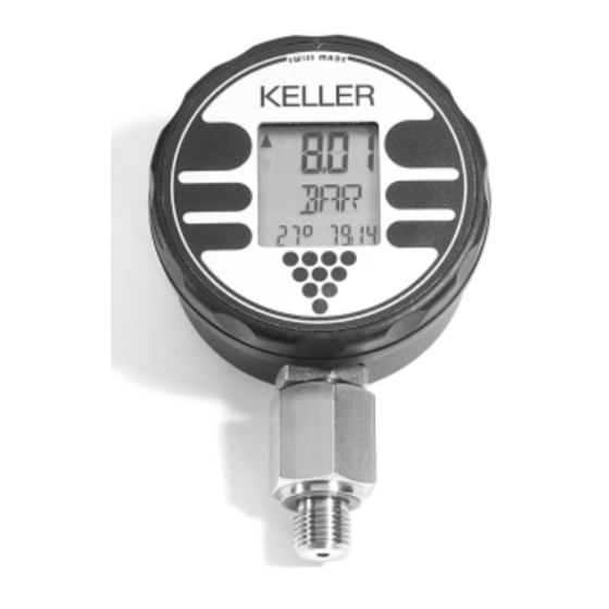
- Page 3 ENERAL ESCRIPTION The KELLER Intelligent Manometer is a precise The face of the Intelligent Manometer can be pressure measuring instrument. Its high accu- rotated through 355 °. This feature allows the racy, solid construction and its long battery life Intelligent Manometer to be mounted in all pos- make it to an ideal measuring instrument, espe- sible positions;...
-
Page 4: Operation
(i.e. 20.00) subsequently called activation. - the software program number on the middle display ( MR 01) - the year and calendar week of the program version (94:23) on the lower right display KELLER... - Page 5 OMMAND TRUCTURE The Mano-Mode is the standard mode of the The following commands, appearing in the shown Intelligent Manometer. Since the function of order, can be activated from the Mano-Mode: secondary displays can be selected (see Dise- Mode), the individual segments are described Mano-Mode with the peak- and trough pressure display: resets the peak- and...
- Page 6 The zero of the system can be adjusted with the The Intelligent Manometer may be supplied fit- command ZERO. ted with two sensors. Within ZERO, one has the possibility to switch back and forth between the Activate ZERO. two sensors with the command EXE. The arrow The display shows: on the upper left display points upwards if sen- - Upper display: Actual pressure...
- Page 7 MECY ( MEsure CYcle ) = Adjusting the measuring cycle. The measuring cycle can be adjusted between Activating RES programmes the new selected once per second up to once per hour ( 59 : 59 ). measuring cycle and switches back to the Mano- Longer measuring cycles extend the battery life.
- Page 8 ECORD ONLY DISE ( DIsplay SElect ) = Selection of Display Display Select enables the selection of the dis- The selected configuration is valid for both the play position, and allocates the measured para- Mano-Mode and the Record-Mode. meter to the chosen display. There are three selectable display positions: Please note that not all possible combinations Upper Display / Lower Left / Lower Right.
- Page 9 ECORD ONLY Programming of the display: After activating DISE, the instrument displays the actual settings. The display that is now flas- hing can be changed by activating EXE. STEP If another display possibility is to be adjusted, activate STEP. STEP When all possibilities are defined to your needs, you may return to the new configured Mano- Mode from any position within DISE by activa-...
- Page 10 ECORD ONLY SAVS ( SAVe Select ) = Selection of the values to be stored in the Record-Mode. The settings programmed in DISE, which are now active, can be selected for storage under SAVS. Only the variables which are selected under SAVS will later actually be stored in the Record-Mode.
- Page 11 ECORD ONLY RECS ( REcord SElect ) = Preparing the storage The value of the flashing digit can be increased parameters with the command EXE. Activating RECS leads either to Rec-Sel- or to STEP switches to the next digit which may be the Rec-Cont-Mode.
- Page 12 ECORD ECORD ONLY In the Record-Mode, the measured values can The actual measured values are not shown bet- be stored. The measured parameters ( see ween two recordings. They can be displayed by SAVS-Mode), the number of measurements activating EXE, without interrupting the recor- and the interval ( in minutes and seconds ) are ding.
- Page 13 OUT OF THE TORED ALUES ECORD ONLY The transfer of the data always starts at the last RANSFER TO ( only with Logger-Option): recording and can be extended to read out the In order to transfer the data from the Intelligent entire memory.
- Page 14 If the Intelligent Manometer program appears to this point, we recommend changing the battery. be locked (the instrument will not respond to The batteries can be acquired from KELLER. front key operations). This can be rectified by disconnecting the battery for a period of longer After a battery change, it is possible that the than 20 seconds.
-
Page 15: Analog Output
NSTRUMENTS WITH NALOG UTPUT The Intelligent Manometer may be supplied fit- Rear Side: ted with an optional 0…10 V or 4…20 mA ana- log signal output. The analog signal output must be powered from an external DC supply. The signal output will only function when the supply is connected, it is completely independent of the Intelligent Manometer’s battery powered measuring cir-... - Page 16 ECHNICAL Total Accuracy of displayed Pressure typ. ± 0,1 % FS, ± 1 Digit ( at 20 °C ) max. ± 0,3 % FS, ±1 Digit ( from 0…50 °C ) Overpressure FS + 20 % Measurement Cycle 1 Measurement per Second Displayed Temperature Temperature of Reference Sensor in °C Storage Temperature...
- Page 17 RESSURE ENERATION PTIONS P 12 RESSURE - Pressure generation up to 700 bar - Pressure media: Hydraulic oil ( 148 cm - High volume calibration - Fine adjustment valve - Ideal test equipment for manometers and pressure transmitters HTP 1 RESSURE ANDPUMP - Pressure generation up to 700 bar...
-
Page 18: Declaration Of Conformity
As criteria for the electromagnetic compatibility, the following norms are applied: EN - 50081 - 1 EN - 50082 - 1 This declaration is given for the manufacturer KELLER AG für Druckmesstechnik St. Gallerstrasse 119 CH - 8404 Winterthur in full responsibility by... -
Page 19: Your Notes
OTES...
Need help?
Do you have a question about the MANO GAUGE and is the answer not in the manual?
Questions and answers