
Subscribe to Our Youtube Channel
Related Manuals for Pro's Kit MT-3209


Summary of Contents for Pro's Kit MT-3209
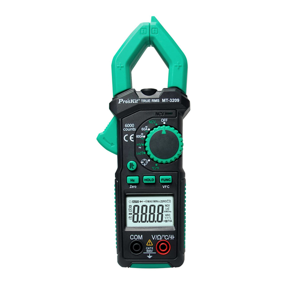
- Page 1 MT-3209 3 5/6 AC/DC Digital Clamp Meter User’s Manual Edition, © 2021 Copyright by Prokit’s Industries Co., Ltd.
- Page 2 Safety Information Warnings Special attention shall be paid when using the meter, improper use might cause an electric shock or damage the meter. General safety procedures shall be followed during the use and safety measuring methods regulated by the instruction manual shall be completely respected.
- Page 3 Use a damp cloth and mild detergent to clean the meter; do not use abrasive cleaning agents or solvents. Power supply of the meter should be turned off when not in use, range switch to the OFF position. ...
-
Page 4: Specifications
DC, AC voltage or Ampere Connected / Disconnect indication Low battery Automatic shutdown indication Automatic range measurement mode Data hold status Hz, KHz Hertz, Kilohertz Duty cycle Diode test Ω, kΩ, MΩ Ohm, Kilohm, Megohm (resistance) Volt (voltage), Ampere (current) mF, μF, nF Farad, the unit of capacitance. - Page 5 Sampling time: About 3 times/s Automatic power off time: 15 minutes Power supply: 1.5V AAA battery ×2 Battery low voltage indication: LCD display symbol. Temperature coefficient: < 0.1×Accuracy/℃ Working temperature: 18℃ ~ 28℃ Storage temperature: -10℃ ~ 50℃ ...
- Page 6 AC Voltage Measurement range Resolution Accuracy 0.001V (1.0% reading +5 digits) 0.01V 600V 0.1V (1.2% reading +10 digits) Input impedance: 10M Maximum input voltage: 600V AC (valid value) Frequency response: 40Hz-1kHz True-RMS LoZ V DC & AC Voltage Measurement range Resolution Accuracy...
- Page 7 Resistance Resolution Measurement range Accuracy 600 0.1 6k 0.001k 60k 0.01k (0.8% reading +5digits) 600k 0.1k 6M 0.001M 60M 0.01M (1.2% reading +5digits) Overload protection: 250V DC or AC (valid value) Capacitance Measuring range Resolution Accuracy 0.001nF ± (5.0%reading +15 digits) 60nF 0.01nF 600nF...
- Page 8 Operation Guide 4.1 Measurement Preparations Turn the transfer switch to the desired measurement position, turn on the power. If the battery voltage is low (of about ≤2.4V), the LCD will show “ ”symbol, then the battery shall be replaced. 4.2 Readings Hold During the measuring process, if the readings are required to hold, press “Hold “...
- Page 9 Note: Clamp two lines of the measured circuit or more at the same time will not obtain correct measurement results. To obtain accurate readings, try to enable the measured cable in the middle position of the current clamp. ...
- Page 10 4.7 DC Voltage or AC Voltage Measurement To avoid any electric shock and/or damage to the meter, do not attempt a voltage measurement if the voltage (valid value) is over 600V DC or AC current. To avoid any electric shock and/or damage to the meter, don't attempt to impose between any public terminals and ground any voltage whose valid value is over 600V for DC or AC current.
- Page 11 4.9 Frequency Measurement Pass V position: 1) Turn the switch to “ V” and press “FUNC” to choose ACV, and then press “Hz” to choose Hz. 2) Connect the black test lead to the COM jack and the red lead to the V/ jack. 3)...
- Page 12 3) Connect the test leads to the positive and negative poles of the diode to be tested respectively. 4) The meter displays the forward bias value of the diode to be tested. If the polarity of the test lead is reversed, the meter will display “O.L”. 4.12 Beep Continuity Test 1)...
-
Page 13: Maintenance
Maintenance 5.1 Replace Battery Warnings Before opening the battery cover of the meter, the test lead shall be moved from the measuring circuit first to prevent the risk of electric shock. 1) If “ ” symbol appears, it means the battery shall be replaced. 2)... - Page 14 MT-3209 鉗形電錶使用說明書 聲明 根據國際版權法,未經允許和書面同意,不得以任何形式(包括存儲和檢索或翻譯為其他 國家或地區語言)複製本說明書的任何內容。本說明書在將來的版本中如有更改,恕不另 行通知。 警告 “警告”標誌表示會對用戶造成危險的狀況和操作。它要求在執行此操作時必須注意,如 果不正確執此行操作或不遵守此操作步驟,則可能導致人身傷害或傷亡。在不滿足這些條 件或沒有完全理解的情況下,請勿繼續執行警告標誌所指示的任何操作。 使用儀錶前,請仔細閱讀說明書並注意有關安全警告資訊。 安全須知 本儀錶符合 IEC-61010-1,IEC-61010-2-030, IEC-61010-2-032 電子測量儀器安全儀 器要求過電壓標準 600V CATⅡ和污染等級 2 的安全標準。請遵循本說明書使用儀錶,否 則儀錶所提供的保護功能可能會降低或無效。 安全操作規範 警告 為了避免可能的觸電或人身傷害,請切實遵守以下的規範: 使用儀錶前,請先閱讀“安全須知”。並嚴格按照規定使用儀錶,否則儀錶所提供的 保護能力可能會降低或無效。 使用儀錶前先檢查外殼。檢查是否存在裂紋或塑膠件缺損。仔細檢查輸入端子附近的 絕緣體。 若儀錶工作不正常或損壞,請勿使用。 禁止觸摸電壓超過 30V 真有效值交流電 、42 V 交流電峰值或 60V 直流電的帶電體。...
- Page 15 安全符號: 儀錶錶體及使用說明書中使用的符號: 警告,重要的安全標誌,使用前應參閱使用說明書。錯誤使用可能致 設備或它的部件的損壞 雙重絕緣保護 接地 通用技術指標 全量程過載保護 使用環境條件: IEC-61010-1,IEC-61010-2-030, IEC-61010-2-032 600V CATⅡ,污染等級 2 海拔高度 < 2000 m 工作環境溫濕度:18~28℃(<75% RH) 儲存環境溫濕度:-10~50℃(<70% RH, 取出電池) 溫度係數:0.1準確度/℃ 測量端和地之間允許的最大電壓:600V 直流或交流有效值 採樣速率:約 3 次/秒 顯示:3 5/6 位液晶顯示幕 鉗口開口尺寸:30mm ...
- Page 16 LCD 顯示符號 直流,交流(電壓/電流) 通斷指示 電池不足 自動關機指示 自動量程模式 讀數保持狀態 Hz,KHz 頻率單位 赫茲,千赫茲 占空比 二極體測試 Ω, kΩ, MΩ 電阻單位 歐姆 千歐姆、兆歐姆 電壓單位 伏特 電流單位 安培 mF, μF, nF 電容的單位;F: 法拉,mF:毫法,μF: 微法, nF: 納法 ℃/℉ 溫度單位,攝氏度℃ 華氏度℉ 非接觸電壓探測 低阻抗電壓測量 變頻器電源測量 技術指標 6.1 交流電流 ...
- Page 17 6.2 直流電流 量程 解析度 準確度 0.01A (3.0% 讀數 + 15 字) 600A 0.1A (3.0% 讀數 + 5 字) - 最大輸入電流:600A AC 電流 - 過載保護:250V 交流或直流真有效值. 6.3 直流電壓 量程 解析度 準確度 600mV 0.1mV 0.001V (0.5%讀數+5 字) 0.01V 600V 0.1V (0.8%讀數+5 字)...
- Page 18 6.6 頻率 通過 V 檔: • 量程 解析度 準確度 600Hz 6KHz 0.001KHz (1.5% 讀數 + 5 字) 60KHz 0.01KHz 600KHz 0.01KHz - 輸入信號範圍:0.6V ~ 600V 超載保護:600V DC 或 AC(有效值) 鉗頭測頻(通過 A 檔): • 量程 解析度 準確度 600Hz (1.5% 讀數 + 5 字) - 輸入信號範圍:...
- Page 19 6.10 二極體及線路通斷測試 功能 測試條件 正向直流電流:約 1.2mA;開路電壓:約 3.2V。 二極體測試 顯示器顯示二極體正向壓降的近似值。 當被測電阻小於約 30時,蜂鳴器響 - 超載保護:250V DC 或 AC(真有效值) 操作指南 7.1 開機及測量準備 撥動轉換開關開機。如果電池電壓不足(約≤2.4V),顯示器將顯示“ ”符號,應 更換電池。 7.2 讀數保持 在測量的過程中,如需要讀數保持,輕觸“Hold”鍵,顯示器的顯示值將被鎖住,再次 輕觸“Hold”鍵,可解除讀數保持。 7.3 背光和輔助照明 1)在測量的過程中,如果環境光線太暗,致使讀數困難,可按“BL/FL”,打開背光源,約 30 秒鐘後自動關閉,或再次按“BL/FL”鍵關閉。 2) 按“BL/FL”鍵約 2 秒,打開輔助照明 LED,同時開啟背光源,約 30 秒鐘後自動關閉, 或在此期間短按“BL /FL”鍵關閉。...
- Page 20 注意: 1)同時夾住被測線路的兩根或更多導線不能獲得正確的測量結果。 2)為獲得準確的讀數,應盡可能使被測導線處於電流鉗中心位置。 3)測量變頻器供電電流,可在 AC A 測量模式下長按 FUNC/VFC 鍵,切換到 VFC 模式測 量。 7.6 非接觸電壓探測(NCV) 1)將旋轉開關旋至 NCV 檔位。 2)將儀錶鉗頭感應區靠近被測導線 , 儀錶可以探測被測導線是否存在 ≥90V 交流電壓。當儀錶探測到交流電壓信號時,蜂鳴器報警同時 NCV LED 閃爍。 注意: 即使沒有報警指示,電壓仍然可能存在。不要依靠非接觸電壓探測 器來判斷導線是否存在電壓。探測操作可能會受到插座設計、絕緣 厚度類型不同等因素的影響。 7.7 直流電壓或交流電壓測量 本儀錶直流或交流電壓量程為:DC: 600mV、6V、60V、600V; AC: 6V、60V、600V 。 不可測量任何高於...
- Page 21 通過電流檔測量 1)將旋轉開關旋至 60A 或 600A 檔位, 2)按 FUNC 鍵選擇 ACV,然後按“Hz”鍵選擇 Hz 測量。 3)握住扳機,張開鉗頭,把被測線路的一根導線夾在鉗內。 4)當被測信號≥6A 時,儀錶顯示幕顯示測量的頻率(Hz)值。 7.10 電阻測量 1) 將旋轉開關旋至 檔位。 2) 分別把黑色錶棒和紅色錶棒連接到 COM 插座和 V/輸入插座。 3) 用錶棒探針分別與待測電阻兩端連接,測量待測電阻的值。 注意: 在電路上所測量到的電阻值通常會和電阻的額定值有所不同。 在測量低電阻時,為了測量準確請先短路兩錶棒讀出錶棒短路的電阻值,在測量被測電阻 後需減去該電阻值。 當儀錶開路時,顯示器將顯示“O.L”,表示測量值超出量程範圍。 7.11 二極體測量 ...
- Page 22 保養 更換電池 警告 在打開儀錶的電池蓋之前,應將錶棒從測量電路移開,以避免電擊危險。 1) 如果“ ”符號出現,它表明應更換電池。 2) 旋開儀錶電池蓋的緊固螺釘並將其移開。 3) 將舊電池更換。 4) 將電池蓋按原樣裝上。 注意: 電池的極性不可裝反。 更換錶棒 警告 更換錶棒時,必須更換同樣的或相同等級的錶棒。錶棒必須完好, 錶棒的等級:1000V 10A。 若錶棒絕緣層損壞,如導線的金屬絲裸露,必須更換錶棒。 配件 1. 使用說明書 3. K 型溫度感應探頭 2. 測量錶棒 X 1 對...
- Page 23 MT-3209 钳形电表使用说明书 声明 根据国际版权法,未经允许和书面同意,不得以任何形式(包括存储和检索或翻译为其他 国家或地区语言)复制本说明书的任何内容。本说明书在将来的版本中如有更改,恕不另 行通知。 警告 “警告”标志表示会对用户造成危险的状况和操作。它要求在执行此操作时必须注意,如 果不正确执此行操作或不遵守此操作步骤,则可能导致人身伤害或伤亡。在不满足这些条 件或没有完全理解的情况下,请勿继续执行警告标志所指示的任何操作。 使用仪表前,请仔细阅读说明书并注意有关安全警告信息。 安全须知 本仪表符合 IEC-61010-1,IEC-61010-2-030, IEC-61010-2-032 电子测量仪器安全 仪器要求过电压标准 600V CAT Ⅱ和污染等级 2 的安全标准。 请遵循本说明书使用仪表,否则仪表所提供的保护功能可能会降低或无效。 安全操作规范 警告 为了避免可能的触电或人身伤害,请切实遵守以下的规范: 使用仪表前,请先阅读“安全须知”。并严格按照规定使用仪表,否则仪表所提供的 保护能力可能会降低或无效。 使用仪表前先检查外壳,检查是否存在裂纹或塑料件缺损。请仔细检查输入端子附近 绝缘体。 若仪表工作不正常或损坏,请勿使用。 禁止触摸电压超过 30V 真有效值交流电、42 V 交流电峰值或 60V 直流电的带电体。...
- Page 24 安全符号: 仪表本体及使用说明书中使用的符号: 警告,重要的安全标志,使用前应参阅使用说明书。错误使用可能导 致设备或其部件损坏。 双重绝缘保护 接地 通用技术指标 自动选择功能及量程: 全量程过载保护 使用环境条件: IEC-61010-1,IEC-61010-2-030, IEC-61010-2-032 海拔高度 < 2000 m 工作环境温湿度:18~28℃(<75% RH) 储存环境温湿度:-10~50℃(<70% RH, 取掉电池) 温度系数:0.1准确度/℃ 测量端和地之间允许的最大电压:600V 直流或交流有效值 采样速率:约 3 次/秒。 显示:3 5/6 位液晶显示屏。 钳口开口尺寸:30mm 超量程指示:液晶显示器将显示“O.L”。 电池低压指示:当电池电压低于正常工作电压时,“ ”将显示在液晶屏幕上。 输入极性指示:自动显示“”号 自动关机时间:15 分钟 ① 电源: 2x1.5V AAA 电池 ⑪...
- Page 25 LCD 显示符号 直流,交流(电压/电流) 通断指示 电池不足 自动量程模式 自动关机指示 读数保持状态 V mV 电压单位 伏特 毫伏 电流单位 安培 Hz,KHz 频率单位 赫兹,千赫兹 占空比 二极管 Ω kΩ MΩ 电阻单位 欧姆 千欧 兆欧 mF,μF, nF 电容单位;F: 法拉,mF:毫法,μF:微法,nF: 纳法, ℃/℉ 温度单位,摄氏度 ℃ 华氏度℉ 非接触电压探测 低阻抗电压测量 变频电源测量...
- Page 26 技术指标 6.1 交流电流 量程 分辨率 准确度 0.01A (2.5 % 读数 + 5 字) 600A 0.1A - 最大输入电流:600A AC 电流; - 超载保护 250V DC 或 AC(有效值) - 频率响应范围:40~1KHz;True RMS 真有效值测量显示 6.2 直流电流 量程 分辨率 准确度 (3.0 % 读数 + 15 字) 0.01A (3.0 % 读数...
- Page 27 6.5 LoZ V 直流或交流低阻抗电压测量 量程 分辨率 准确度 (2.0%读数+3 字) DC 600V 0.1V (2.0%读数+3 字) AC 600V 0.1V - 最大输入电压:600V AC (有效值) - 输入阻抗 1MΩ - 频率响应范围:40Hz~1KHz ; 正弦波平均值响应 6.6 频率 • 通过 V 檔: 量程 分辨率 准确度 600Hz 6KHz 0.001KHz (1.5% 读数...
- Page 28 量程 分辨率 准确度 0.001nF ± ( 5.0% 读数+15 字 ) 60nF 0.01nF 600nF 0.1nF 6μF 0.001μF ± ( 4.0% 读数+5 字 ) 60μF 0.01μF 600μF 0.1μF 0.001mF ± ( 5.0% 读数+5 字 ) 100mF 0.01mF - 过载保护:250V DC 或 AC(有效值) ...
- Page 29 闭,或在此期间再次按“BL/FL”键关闭背光。 7.4 自动关机 1) 开机后的 15 分钟内无任何操作时,仪表会进入休眠状态,自动关机以节省电能,关机 前 1 分钟,蜂鸣器“嘀嘀嘀”声提示。 2) 自动关机后,按任意键,唤醒仪表进入工作状态。 7.5 交流电流测量 1) 旋转开关旋转到 60A 或 600A 档位(根据估计测量电流值大小选择)。 2) 握住扳机,张开钳头,把被测线路的一根导线夹在钳内。 3) 当被测信号≥0.05A 时,仪表主显示屏显示测量的电流值。 4) 如测量变频电源供电的交流电流, 可在 ACA 测量模式下长按 FUCN/VFC 键切换到 VFC 电流测量,确保测量数据准确。 注意: 1)同时夹住被测线路的两根或更多导线不能获得正确的测量结果。 2)为获得准确的读数,应尽可能使被测导线处于电流钳头中心位置。 ...
- Page 30 旋转开关旋至 NCV 檔位,将仪表钳头感应区靠近被测导线, 仪 表可以探测被测导线是否存在≥90V 交流电压。 当仪表探测到 交流电压时,仪表蜂鸣器报警同时 NCV LED 燈闪烁。 注意: 即使没有报警指示, 电压仍然可能存在。 不要依靠非接触电压 探测器来判断导线是否存在电压。 探测操作可能会受到插座设 计、绝缘厚度类型不同等因素的影响。 7.7 直流电压或交流电压测量 本仪表直流或交流电压量程为:DC: 600mV、6V、60V、600V; AC: 6V、60V、600V 。 如测量变频器供电电压,可在 ACV 测量模式下,长按 VFC 键,切换到 VFC 模式测量, 确保测量数据准确. 测量交流或直流电压: 1)将旋转开关旋至 V 档位,按 FUNC 键选择 DCV 或 ACV 测量。 2)分别把黑色测试笔和红色测试笔连接到...
- Page 31 3) 当被测信号≥6A 时,仪表显示屏显示测量的频率(Hz)值。 7.10 电阻测量 1)将旋转开关旋至 档位。 2)分别把黑色测试笔和红色测试笔连接到 COM 插座和 V/输入插座。 3)用测试表笔探针分别与待测电阻两端连接,测量待测电阻的值。 注意: 在电路上所测量到的电阻值通常会和电阻的额定值有所不同。 在测量低电阻时,为了测量准确请先短路两表笔读出表笔短路的电阻值,在测量被测电阻 后需减去该电阻值。 当仪表开路时,显示器将显示“O.L”,表示测量值超出量程范围。 7.11 二极管测量 1)将旋转开关旋至 档位,按 FUNC 键选择 测量。 2)分别把黑色测试笔和红色测试笔连接到 COM 插座和 V/输入插座。 3)分别把黑色表笔和红色表笔连接到被测二极管的负极和正极。 4)仪表显示被测二极管的正向偏压值。如果测试笔极性接反,仪表将显示“O.L”。 5)在电路里,正常的二极管仍应产生 0.5V 到 0.8V 的正向压降;但反向偏压的读数将取决 于两表笔之间其他通道的电阻值变化。...
- Page 32 7.14 溫度測量 1)将旋转开关旋至℃/℉档位。按“FUNC” 键选择℃或℉测量功能,仪表将显示周围环境 温度。 2)分别把热电偶的正负极性连接到 COM 插座和 V/输入插座,测温探头接触待测物体表 面。 由液晶显示器读取测量温度值。 保养 更换电池 警告 在打开仪表的电池盖之前,应将表笔从测量电路移开,以避免电击危险。 1)如果“ ”符号出现,它表明应更换电池。 2)旋开仪表电池盖的紧固螺钉并将其移开。 3)将旧电池更换。 4)将电池盖按原样装上。 注意: 电池的极性不可装反。 更换表笔 警告 更换表笔时, 必须更换同样的或相同等级的表笔。 表笔必须完好, 表笔的等级: 1000V 10A。 若表笔绝缘层损坏,如导线的金属丝裸露,必须更换表笔。...
- Page 33 附件 1. 使用说明书 l X 1 本 3. K 型温度测量感温探头 X 1 只 2. 测量表笔 X 1 付...
- Page 34 中国地区产品保固卡 购买日期 店章 公司名称 联络电话 电子邮箱 联络地址 产品型号 □ MT-3209-C 在正常使用情况下,自原购买日起 12 个月免费维修保证(不含耗材、消耗品)。 ※ 产品保固卡需盖上店章、日期章,其保固效力始生效。 ※ 本卡请妥善保存,如需维修服务时,请出示本卡以为证明。 ※ 保固期满后,属调整、保养或是维修性质之服务,则酌收检修工时费用。若有零件 ※ 需更换,则零件费另计。 产品保固说明 1.保固期限内,如有下列情况者,维修中心则得酌收材料成本或修理费(由本公司维修人 员判定): • 产品表面的损伤,包括外壳裂缝或刮痕。 • 误用、疏忽、不当安装或测试,未经授权打开产品修理,修改产品或者任何其他 超出预期使用范围的原因所造成的损害。 • 因事故、火灾、电力变化、其他危害,或自然灾难所造成的损害。 2.非服务保证内容: • 机件本体外之消耗品:如电池等消耗品 • 机件本体之外之附配件:如表笔、温度测量感温探头、保险丝等附配件。 3.超过保证期限之检修或服务,虽未更换零件,将依公司保固维修政策酌收服务费。 服务电话: 021 68183050 / 68183051/68183052/ 68183053 服务电话: 400-169-9629 服务传真: 021 68183061...
- Page 36 寶 工 實 業 股 份 有 限 公 司 PROKIT’S INDUSTRIES CO., LTD https://www.prokits.com.tw Email: pk@mail.prokits.com.tw ©2021 Prokit’s Industries Co., Ltd. All rights reserved. 2021001...
Need help?
Do you have a question about the MT-3209 and is the answer not in the manual?
Questions and answers