Table of Contents
Advertisement
Quick Links
3 1/2 HAND HELD
DIGITAL CLAMP METER
MT-3266
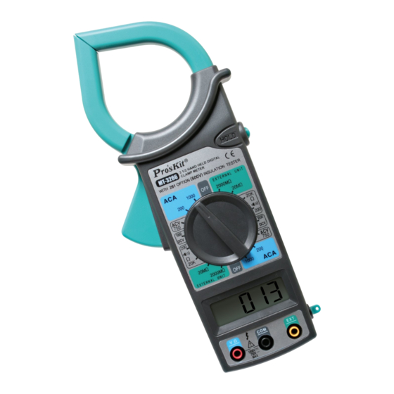
• FRONT PANEL DESCRIPTION:
Hold switch
Clamp
Pressure
Knob switch
LCD
COM terminal
Hand bell
Insulation
V/Ω INPUT terminal
attachment
terminal
• OPERATION:
1. AC current measurement:
a. Set the knob switch to ACA 1000A position.
b. Set the hold switch is loosing state.
c. Press the "PRESSURE" down and clamp a wire. If
DIGITAL CLAMP METER
OPERATION MANUAL
• INTRODUCTION
Clamp meter is 3 1/2 digit LCD and standard 9V battery
operation for measuring DC voltage, AC and DC current,
resistance and continuity test. All overload protection is
provided. It is matching with 500V insulation test attach-
ment for insulation test function. The knob switch design
makes manual operation workable & function selector,
range selector and power switch are all on one knob. It is
a good tool for electric measurement.
• GENERAL SPECIFICATION
1. Display: 3 1/2 digit LCD and max. 1999 counts.
2. Polarity : Auto
3. Over range indication: Only the MSD "1" display.
4. Sampling rate: 3 times per second.
5. Low voltage indication: "LOBAT" sign
6. Hold: Data hold
7. Power: 9V carbon-zinc battery or alkaline battery
8. Battery life: approx. 200 hours (alkaline battery)
Approx. 150 hours (carbon-zinc battery)
clamp two or over wire, measure is useless.
d. If the reading less than 200A, change the range to
"200A" position in order to improve the Resolution.
e. If in dark, press hold switch, and read the data in
light place.
2. AC and DC voltage measurement:
a. Set the knob switch to DCV1000V or ACV750V po-
sition.
b. Set the hold switch is loosing state.
c. Connect the red lead to "V/Ω" jack and the black
lead to "COM" jack.
d. Connect the probes across circuit to be tested.
3. Resistance measurement:
a. Set the knob to proper resistance position.
b. Set the hold switch is loosing state.
c. Connect the red test lead to "V/Ω" jack and the test
black lead to "COM" jack.
d. Connect the probes across resistance to be tested.
e. When checking in-circuit resistance, be sure the cir-
cuit under test has all power removed and that all
capacitor are fully discharged.
4. Continuity test:
4
9. Working environment: 0˚C~50˚C,< 80% RH.
10. Storage environment: -20˚C~60˚C, < 80% RH.
11. Dimension: 230(L)mm x 70(W) mm x 37(D)mm.
12. Weight: approx. 310g (including battery).
13. Max. jaw opening: 50mm
• ELECTRICAL SPECIFICATION:
Accuracy is ± (percentage of reading + number of digit)
at 23±5˚C, <80%RH.
1.AC current
Range
Accuracy
200A
±
(3%+5d)
±
1000A
(3%+5d)
Frequency response: 50~60Hz
Indication: Average (rms of sine wave)
2. DC voltage
Range
Accuracy
1000V
±
(0.8%+2d)
Input impedance: 9MΩ
Max. overload protection: 1000 V DC
3. AC voltage
1
a. Set the knob switch to 200Ωposition.
b. Connect the test lead to "V/Ω" jack and the test black
lead to "COM" jack.
c. If resistance value less than 75Ωbetween two test
leads, buzzer sounds.
5. High resistance measurement:
a. Set the knob switch to "EXTERNAL UNIT" 20MΩ or
2000MΩ position, reading is unstable.
b. Connect three plugs of test attachment to corre-
spond jacks on front panel.
c. Set the knob switch and attachment switch to
2000MΩ position separately.
d. Connect resistance to input terminal of attachment.
e. Set power switch of attachment to "ON" position,
press "PUSH" button, indication lamp is light and
reading. If reading less than 19MΩ, separately
change meter and attachment range switch to
20MΩ in order to resolution.
Note:
1. 500V insulation attachment is optional accessories.
2. If 500V insulation attachment low voltage indication
lamp is light, should replacement battery.
5
Range
Accuracy
750V
±(1.2%+4d)
Frequency response: 50~400Hz
Input impedance: 9MΩ
Max. overload protection: 750 V AC rms
4. Resistance
Range
Accuracy
200Ω
±(1%+3d)
20kΩ
±(1%+1d)
Resolution
Max. overload protection: 250 V DC / AC rms
100mA
5. Continuity test
1A
Range: 200Ω
When resistance less than 75Ω build-in buzzersounds.
Max. overload protection: 250VDC/AC RMS
6. High resistance
ment)
Resolution
Range
Accuracy
1V
20MΩ
±
(2%+2d)
≤500MΩ
2000MΩ
>500MΩ
2
• MAINTENANCE:
1.Your Digital Multi-meter is a preci-
sion electronic device. To avoid dam-
age, do not tamper with the circuitry.
Note:
a. Don't input over 1000VDC or 750Vrms.
b. Don't input voltage signal on resistance range.
c. Before replacement battery, must remove leads
from circuit and be turn off power.
2. Replacement battery:
If appears "LOBAT" on LCD, user should immediately
replace battery.
PROKIT'S INDUSTRIES CO., LTD.
http://www.prokits.com.tw
E-mail : pk@mail.prokits.com.tw
©2014 Prokit's Industries Co., LTD. All rights reserved. 2014001
6
Resolution
1V
Resolution
0.1Ω
10Ω
(with 500V Insulation attach-
Resolution
10KΩ
±
(4%+2d)
1MΩ
±
(5%+2d)
3
7
Advertisement
Table of Contents

Related Manuals for Pro's Kit MT-3266


Summary of Contents for Pro's Kit MT-3266
- Page 1 8. Battery life: approx. 200 hours (alkaline battery) 3. AC voltage ± >500MΩ (5%+2d) MT-3266 Approx. 150 hours (carbon-zinc battery) • FRONT PANEL DESCRIPTION: • MAINTENANCE: clamp two or over wire, measure is useless. a. Set the knob switch to 200Ωposition.
- Page 2 1MΩ 碳鋅電池約150小時 ≦500MΩ±(4%讀數+2字) 最大過載保護: 1000V直流。 >500MΩ(5%讀數+2字) 9. 工作環境 : 溫度0˚C~50˚C 3.交流電壓 相對濕度小于80% 量程 準確度 分辨率 10.儲存環境 : 溫度-20˚C~60˚C MT-3266 相對濕度小于80% c. 按下鉗頭開關打開鉗口,鉗住一根導線,且導線必需通 a. 正常情況, 將開關旋至“EXTERNAL UNIT”20MΩ或 四、外觀說明 中國地區產品保固卡 過鉗口中心,如果鉗住兩根以上,測量無效。 2000MΩ檔,顯示是不穩定的,處於游離狀態。 d. 讀取數值,如果讀數小于200A開關旋到200A檔,以提 b. 測試附件三個插頭分別插入鉗形表的三個插孔。 公司名稱 店章 高準確度,如果因環境條件限制,如暗處無法讀取數值, c. 旋轉開關,測試附件量程開關均置于2000 MΩ位置。...
Need help?
Do you have a question about the MT-3266 and is the answer not in the manual?
Questions and answers