
Related Manuals for Pro's Kit MT-3110


Summary of Contents for Pro's Kit MT-3110
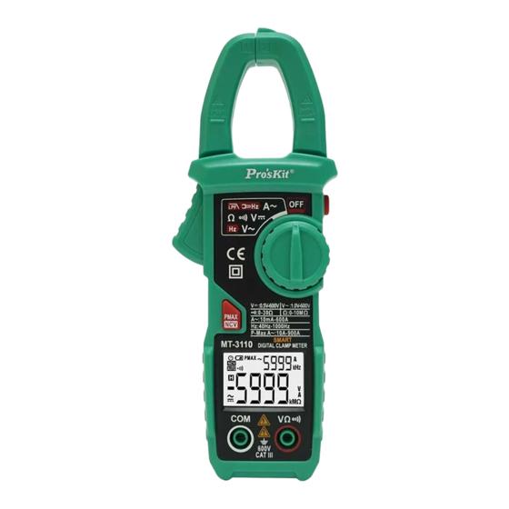
- Page 1 MT-3110 3 5/6 Smart Digital Clamp Meter User’s Manual Edition, © 2016 Copyright by Prokit’s Industries Co., Ltd.
-
Page 2: Safety Information
1.Safety Information Warnings Special attention shall be paid when using the meter, improper use might cause an electric shock or damage the meter. General safety procedures shall be followed during the use and safety measures regulated by the instruction manual shall be completely respected. To fully make use of the functions of the meter and ensure safe operation, please carefully read and follow the use method of this manual. - Page 3 Before opening the meter case or battery cover at the end, the pen-shape meter should be removed from the circuit being measured. To avoid electric shock that might be caused by erroneous readings, when the meter displays “ ” symbol, the battery should be replaced immediately. Use a damp cloth and mild detergent to clean the meter, do not use abrasive cleaning agents or solvents.
-
Page 4: Specifications
2.2 Instructions to rotary switch and key as well as input socket OFF: Meter OFF position Measuring position DC voltage, AC voltage, resistance and buzzer input terminals Current input into mutual inductor 2.3 LCD Display Unit AC, DC Connected disconnect indicate AUTO AutoScan Mode Maximum peak current measurement... - Page 5 Overload protection for the whole measurement range. Maximum allowable voltage between the measuring terminal and the Earth: 600V DC or 600V AC Work height: maximum 2000m Display: LCD Maximum display value: 6000 digits. Polar indication: automatically indicate,‘-’ means negative polarity. Over range Indication: ‘0L’...
- Page 6 Measurement range Distinguish ability Accuracy degree 0.001V 0.5% reading +3 word 0.01V 0.1V Minimum input voltage: 0.5V DC Maximum input voltage: 600V DC AC Voltage Measurement range Distinguish ability Accuracy degree 0.001V 0.8% reading +5 word 0.01V 600V 0.1V Minimum input voltage: 1.0V AC Maximum input voltage: 600V AC (effective value) Frequency range: 45 ~ 65Hz Frequency...
-
Page 7: Auto Power Off
Resistance Measurement range Distinguish ability Accuracy degree 6k 0.001k 0.8% reading +3 word 60k 0.01k 600k 0.1k 6M 0.001M 10M 0.01M Overload protection: 600V DC or AC (effective value) Line on-off test Measurement range Distinguish ability Functions 1 If the resistance of circuit being measured is less than 50±30, then the... -
Page 8: Measurement Preparations
3)When turn the meter on, hold the "PMAX/NCV" key at the same time, then the auto power off function is canceled. 4.4 Measurement Preparations 1)Turn the transfer switch, turn on the power. If the battery voltage is low (of about ≤2.4V), the LCD will show“ ”symbol, then the battery shall be replaced. -
Page 9: Non-Contact Voltage Detection (Ncv)
Note: 1) Clamp two lines of the measured circuit or more at the same time will not obtain correct measurement results. 2) To obtain accurate readings, try to enable the measured cable in the middle position of the current clamp. 3)... -
Page 10: Dc Voltage Measurement
2) When measured signal >0.01A, the main LCD of the meter displays the measured current value, the vice LCD displays current frequency (Note: only when current value >0.2A could the meter displays its frequency value) 4.8 DC Voltage Measurement 1) Connect the pen-shaped meter to the measured signal, when the measured signal =0.5V, will the meter display current measuring DC voltage value. -
Page 11: Resistance Measurement
4.10 Resistance Measurement 1) Connect the pen-shaped meter to the measured resistance, when the measured resistance >10M, the meter will display----, when the measured resistance is less than 50, the meter buzzer will send out alarm sound. 4.11 Measure AC current and AC voltage at the same time 1)... - Page 12 4.12 Measure AC current and DC voltage at the same time 1) Hold the trigger, open the clamp head and clamp one cable of the measured circuit, when the measured signal >0.01A, the meter vice LCD will display measured current value. 2)...
-
Page 13: Maintenance
5. Maintenance 5.1 Replace Battery Warnings Before opening the battery cover of the meter, the pen-shape meter shall be moved from the measuring circuit first to prevent the risk of electric shock. 3) If “ ” symbol appears, it means the battery shall be replaced. 4)...
Need help?
Do you have a question about the MT-3110 and is the answer not in the manual?
Questions and answers