Advertisement
EVERLAST
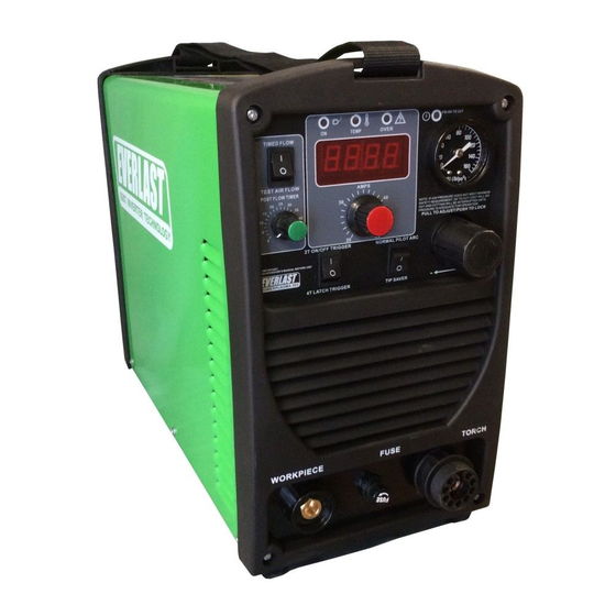
POWER PLASMA 50S
50 Amp IGBT Plasma Cutter
CC
PAC
IGBT
1
~
PHASE
DC
DV
120/240V
Operator's Manual For
PowerPlasma 50S
Safety, Setup and General Use Guide
Rev. 2
0 00327-18ETL
everlastwelders.com
Specifications and Accessories subject to change without notice.
1-877-755-9353
329 Littlefield Ave. South San Francisco, CA 94080 USA
Advertisement

Related Manuals for Everlast POWER PLASMA 50S


Summary of Contents for Everlast POWER PLASMA 50S
- Page 1 EVERLAST POWER PLASMA 50S 50 Amp IGBT Plasma Cutter IGBT PHASE 120/240V Operator’s Manual For PowerPlasma 50S Safety, Setup and General Use Guide Rev. 2 0 00327-18ETL everlastwelders.com Specifications and Accessories subject to change without notice. 1-877-755-9353 329 Littlefield Ave. South San Francisco, CA 94080 USA...
-
Page 2: Table Of Contents
The owner of this product assumes all liability for its use and maintenance. Everlast Power Equipment INC. does not warrant this product or this document for fitness for any particular purpose, for performance/accuracy or for suitability of application. - Page 3 Dear Customer, THANKS! You had a choice, and you bought an Everlast. We appreciate you as a customer and hope that you will enjoy years of use from your welder. Please go directly to the Everlast website to register your unit and receive your warranty information. Your unit registration is important should any information such as product updates or recalls be issued.
- Page 4 Serial number: ____________________________ Model number: ____________________________ Date of Purchase:__________________________ Contact Information Everlast US: Everlast consumer satisfaction email: sales@everlastwelders.com Everlast Website: everlastwelders.com Everlast Technical Support: support@everlastwelders.com Everlast Support Forum: http://www.everlastgenerators.com/forums/index.php Main toll free number: 1-877-755 WELD (9353) Hours: 9am-5pm PST M-F 11am-4pm PST Sat.
-
Page 5: Safety Precautions
Safety Precautions Everlast is dedicated to providing you with the best possible equipment and service to meet the demanding jobs that you have. We want to go beyond merely delivering a satisfactory product to you. That is the reason we offer free technical support to assist you with your needs should an occasion occur. - Page 6 SAFETY PRECAUTIONS These safety precautions are for protection of safety and health. Failure to follow these guidelines may result in serious injury or death. Be careful to read and follow all cautions and warnings. Protect yourself and others. Welding and cutting processes produce high levels of ultraviolet (UV) radiation that can cause se- vere skin burn and damage.
- Page 7 SAFETY PRECAUTIONS WARNING! Persons with pacemakers should not weld, cut or be in the welding area until they con- sult with their physician. Some pacemakers are sensitive to EMF radiation and could severely mal- function while welding or while being in the vicinity of someone welding. Serious injury or death may occur! Welding and plasma cutting processes generate electro-magnetic fields and radiation.
- Page 8 SAFETY PRECAUTIONS continued WARNING! Electrical shock can kill. Make sure all electrical equipment is properly grounded. Do not use frayed, cut or otherwise damaged cables and leads. Do not stand, lean or rest on ground clamp. Do not stand in water or damp areas while welding or cutting. Keep work surface dry. Do not use welder or plasma cutter in the rain or in extremely humid conditions.
-
Page 9: Introduction And Specifications
NOTE: Accessory and consumable style and quantities are subject to change without notice. Consumable starter kits provide only enough consumables to get started. Extra consumables can be purchased through Everlast or through other local and online iPT 60 Innotec dis-... - Page 10 Plan the unit’s daily use around the recommended average cut thickness for best results and speed. This is an industry standard recommendation and is not unique to Everlast PowerPlasma models. CNC cut thickness is further reduced as it is typically a 100% duty cycle operation which will require a lower maximum amp setting.
-
Page 11: General Overview
Section 1 Introduction and Specifications General overview: The PowerPlasma 50S utilizes the lat- tionally toward the machine, particularly in grinding and est in inverter design technology. It’s a portable dual welding operations. Make sure the control panel is pro- voltage plasma cutter with an output of 50 amps on tected from damage. -
Page 12: Quick Setup Guide, Plasma Connections
When using the plasma cutter at amp levels lower than 40 amps, the nozzle (tip ) will need to be changed out for one with a smaller diameter orifice. While Everlast is the supplier of the torch, it is not the manufacturer. Everlast has a considerable inventory of standard replacement consumables and consumable kits. - Page 13 Section 2 QUICK SETUP AND USE GUIDE STOP: DO NOT FIRE THE TORCH WITH THE TRIGGER TO SET THE OPERATINGAIR PRESSURE. USE THE “CONSTANT FLOW” FEATURE TO SET CUTTING PRESSURE. DO NOT CHANGE CONSUMABLES WHILE THE UNIT IS SWITCHED ON. SERIOUS SHOCK, BURN OR INJURY MAY RESULT IF THE CUP-IN-POSITION SENSOR IN THE TORCH HEAD WERE TO STICK OR MALFUNCTION! Having trouble setting your unit for best cutting? Try the following: Keep your standoff to less than 1/8”.
- Page 14 Section 2 QUICK SETUP AND USE GUIDE QUICK SETUP GUIDE: REAR CONNECTIONS FOR PLASMA OPERATION Compressor and Dryer Diagram Compressor and Air hose w fittings (Customer Supplied) Regulator Assembly with built-in water trap and dirt filter (Included) 1/4” Automotive Universal style quick connector (Included) PUSH TO CONNECT Air Dryer/Oil Filter...
-
Page 15: Front Panel Features And Controls
Section 2 QUICK SETUP AND USE GUIDE FRONT PANEL FEATURES AND CONTROLS 1. ON/TEMP/O.C./OK-TO-CUT 2. AMP DISPLAY 12. AIR PRESSURE 3. CONSTANT FLOW/TIMED FLOW 4. POST FLOW TIME 5. AMP CONTROL 11. AIR PRESSURE ADJUSTMENT 6. 2T/4T TRIGGER LATCH 7. NORMAL/TIP SAVER WORK PIECE FUSE TORCH... - Page 16 Check the wiring for proper conections, output, gauge and length. Once remedied, reset the unit by cycling the on/off switch. If the “Over” light does not clear, contact Everlast. The OK-TO-CUT light remains on while the air pressure is above the minimum threshold pressure. This is not a warning light, but rather it gives the operator assurance that the pressure is within tolerable limits to prevent torch damage.
-
Page 17: Rear Panel Features And Controls
Section 2 QUICK SETUP AND USE GUIDE REAR PANEL FEATURES AND CONTROLS 5. REGULATOR ASSY. 1. BREAKER/ POWER SWITCH 1~220 V INLET 4. GAS INLET 2. POWER CABLE 1 ~ 120/240V 3. HF GROUND BOLT... - Page 18 5% is preferred. Operating the unit on square wave output or modified sine wave generator is strictly prohibited. Contact the manufacturer of the generator for this information. Everlast does not have an “approved” list of generators. But, if the generator is not listed as clean power by its manufacturer, then operation is prohibited.
- Page 19 Section 3 Basic theory and function The design of the blow back start may cause a slight delay in the arc as the air pressure builds inside the torch to create the pressure needed to force the electrode off the nozzle seat. This time will be longer with torches with longer cables.
- Page 20 Section 3 Basic theory and function TIP: To extend consumable life do not use the pilot arc longer than necessary. Use the tip saver feature and do not fire the torch unless you are near the metal and ready to cut. For expanded metal cutting be sure to select “Normal”...
- Page 21 Section 3 Basic theory and function RESULTS OF CUT AT CORRECT SPEED, RESULTS OF CUT AT FAST SPEED AIR PRESSURE AND TORCH ANGLE ROUGH, DISTINCT CUT LINES SPACED FAR APART SMOOTH, EVEN CUT LINES WITH A S REARWARD SWEEP NOTICEABLE SMALL, HARD DROSS MINIMAL EASY TO CLEAN DROSS RESULTS OF TOO MUCH CURRENT OR RESULTS OF CUT AT SLOW SPEED...
- Page 22 Section 3 Basic theory and function AN EXAMPLE OF CUTTING A LEAD-IN WHEN CUTTING OUT A DISK SHAPED OBJECT AN EXAMPLE OF CUTTING A LEAD-IN WHEN CUTTING HOLE IN AN OBJECT When cutting an object, particularly a pattern shape, where the torch must pierce or re-fire in-line at an inter- section of a cut, a lead-in cut should be employed.
- Page 23 Section 4 ipt 60 Torch...
-
Page 24: Troubleshooting
Make sure swirl ring is not cracked. Arc will try to start if touched to the metal, but no air Stuck or dirty solenoid valve. Contact Everlast. flow while switch is pressed. Air flows continuously. - Page 25 *Everlast does not particularly endorse or recommend these brands and is not affiliated with them in anyway. They are mentioned as a common reference only. For specific recommendations regarding connection, contact the manufacturer of the CNC equipment/...
Need help?
Do you have a question about the POWER PLASMA 50S and is the answer not in the manual?
Questions and answers