Chapters
Table of Contents

Related Manuals for Mitsubishi Electric PV-PNS04ATL-IT


Summary of Contents for Mitsubishi Electric PV-PNS04ATL-IT
- Page 1 PV-IB _Eng_IT_Hyoshi 08.3.6 9:49 ページ1 8 3874HC48 6 PHOTOVOLTAIC INVERTER ODEL PV-PNS04ATL-IT PV-PNS06ATL-IT PV-PNS04ATL2-IT PV-PNS03ATL-IT anuale di funzionamento Italiano pp.1-56 Operation anual English pp.57-112...
- Page 2 “Precauzioni di sicurezza” prima di usare l’inverter PV. ●Il manuale dovrebbe essere sempre a disposizione dell’operatore dell’inverter PV. L’inverter PV-PNS04ATL-IT / PV-PNS06ATL-IT / PV-PNS04ATL2-IT / PV-PNS03ATL- IT è progettato in base alle normative definite dalla DK 5940. Pertanto, il propri- etario può...
-
Page 3: Table Of Contents
PV-IB-Italian 08.3.6 10:02 ページ2 Sommario Pagina Presentazione • • • • • • • • • • • • • • • • • • • • • • • • • • • • • • • • • • • • • • • • • • • • • • 1 Precauzioni di sicurezza 5〜7 •... - Page 4 PV-IB-Italian 08.3.6 10:02 ページ3 7 Dati tecnici 47〜52 • • • • • • • • • • • • • • • • • • • • • • • • • • • • • • • • • • • • • • • • • • 7.1 Specifiche 47〜49 •...
-
Page 5: Presentazione
I T / P V - P N S 0 6 A T L - I T / P V - P N S 0 4 A T L 2 - I T / P V - PNS03ATL-IT. Questo manuale illustra il funziona- mento dell’inverter PV PV-PNS04ATL-IT/PV- PNS06ATL-IT/PV-PNS04ATL2-IT/PV-PNS03ATL-IT. -
Page 6: Precauzioni Di Sicurezza
PV-IB-Italian 08.3.6 10:02 ページ5 1 Precauzioni di sicurezza ●I seguenti simboli denotano il tipo e il grado di pericolo che può derivare da un uso errato del dispositivo. Avverte del possibile pericolo di morte AVVERTENZA o di lesioni gravi che si può correre utilizzando l’inverter PV in modo errato. - Page 7 PV-IB-Italian 08.3.6 10:02 ページ6 Avverte di possibili lesioni o danni ATTENZIONE all’edificio o agli oggetti dell’abitazione che possono verificarsi se si utilizza l’inverter PV in modo errato. Non collocare alcun oggetto sull’inverter PV. Non ostruire l’apertura di ventilazione dell’inverter PV. In caso contrario possono svilupparsi incendi e l’utente può...
- Page 8 PV-IB-Italian 08.3.6 10:02 ページ7 ATTENZIONE Evitare di installare l’inverter PV nei seguenti luoghi: (In caso contrario, l’inverter PV può subire guasti oppure può risultare impossibile usarlo in modo sicuro; inoltre, la garanzia del prodotto può risultare invalidata). ・All’esterno, o in luoghi analoghi (※È PROIBITA l’installazione dell’inverter PV in luoghi che non possono essere separati da ambienti esterni, quali ad esempio rimesse aperte su un lato e sprovviste di pareti o porte in grado di bloccare l’apertura).
-
Page 9: Norme Applicabili
(EMC) e alla direttiva per le basse tensioni (LVD) certificata nella dichiarazione CE. Informazioni sullo smaltimento Questo prodotto MITSUBISHI ELECTRIC è stato fabbricato con materiali e componenti di alta qualità, che possono essere riciclati e riutilizzati. Questo simbolo significa che i prodotti elettrici ed elettronici devono essere smaltiti separatamente dai rifiuti casalinghi alla fine della loro vita di servizio. -
Page 10: Configurazione Del Sistema Pv
PV-IB-Italian 08.3.6 10:02 ページ9 3 Configurazione del sistema PV Panoramica del sistema di base ① ② ③ ④ ① ② ③ ④ L’inverter PV converte l’energia elettrica a corrente continua generata dal modulo fotovoltaico (modulo PV) in energia elettrica a corrente alternata e la trasmette alla rete elettrica. - Page 11 PV-IB-Italian 08.3.6 10:02 ページ10 ② Interruttore DC Inserito tra il modulo PV e l’inverter PV, permette di chiudere o aprire il circuito sul lato del modulo ③ Inverter PV Questo modulo converte l’energia elettrica a cor- rente continua generata dal modulo PV in ener- gia elettrica a corrente alternata.
-
Page 12: Parti E Nomi Rispettivi 11〜12
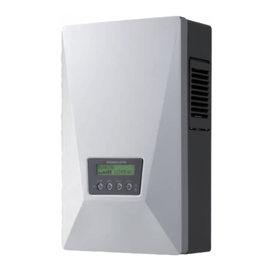
PV-IB-Italian 08.3.6 10:02 ページ11 4 Parti e nomi rispettivi 4.1 Aspetto Pannello anteriore ① ① ① Aperture di ventilazione ② Schermo del pannello ② ③ Passacavi ③ 4.2 Schermo e pulsanti Il dispositivo presenta uno schermo LCD, tre LED e quattro pulsanti. Questi comandi consentono di visualizzare una varietà... -
Page 13: Passacavi
PV-IB-Italian 08.3.6 10:02 ページ12 4.3 Passacavi L’inverter PV dispone dei seguenti passacavi. ④ ① ② ③ assacavi DC Ð ① assacavi DC + ② assacavi AC ③ remistoppa dell'interfaccia RS485 ④ ... -
Page 14: Funzionamento
PV-IB-Italian 08.3.6 10:02 ページ13 Funzionamento Quanto segue illustra il funzionamento dell’inverter PV. 5.1 Procedura di funzionamento La procedura di funzionamento per l’avvio e lo stop dell’inverter PV è illustra- ta qui sotto. 5.1.1 Avvio (accensione) Schermo e pulsanti Procedura Quando l’inverter PV è inattivo, pre- mere e tenere premuto il pulsante POWER per due secondi o più. -
Page 15: Stop (Spegnimento)
PV-IB-Italian 08.3.6 10:02 ページ14 5.1.2 Stop (spegnimento) Per interrompere il funzionamento dell’inverter PV, usare la procedura seguente. Schermo e pulsanti Procedura Quando l’inverter PV è in esecuzione, premere e tenere premuto il pulsante I N FUNZ I ONE 1 2 3 4 5 kWh POWER per due secondi o più. -
Page 16: Schermo Lcd E Led
PV-IB-Italian 08.3.6 10:02 ページ15 5.2 Verifica dello stato di funzionamento L’inverter PV visualizza il proprio stato di funzionamento sullo scher- mo LCD e sui LED in base alle sue effettive condizioni operative. Schermo LCD e LED sono inattivi durante la notte o nei momenti in cui la luce solare è... - Page 17 PV-IB-Italian 08.3.6 10:02 ページ16 <Attesa> (accensione) Descrizione POWER GRID ERROR L’inverter PV è nella fase di ATTENDE RE PREGO preparazione alla generazione dell’en- 1 2 3 4 5 kWh ergia. L’inverter PV inizia l’esecuzione. Il livello di irradiazione è tempo- raneamente calato.
- Page 18 PV-IB-Italian 08.3.6 10:02 ページ17 <Generazione> Descrizione POWER GRID ERROR Il dispositivo sta generando energia elettrica. La barra di alimentazione sul lato inferiore N F sinistro dello schermo LCD 1 2 3 4 5 kWh indica l’energia generata nel- l’occasione. ERROR Descrizione POWER GRID ERROR...
-
Page 19: Accensione Del Led Di Errore
PV-IB-Italian 08.3.6 10:02 ページ18 5.2.2 Accensione del LED di errore Se il LED ERROR è illuminato, procedere come segue. Schermo e pulsanti Procedura 1. Premere il pulsante POWER per 2 secondi o più. Questo interrompe l’esecuzione dell’inverter PV. 2. Accertarsi che sia visualizzato il messaggio “----”, quindi premere nuovamente il pulsante POWER per due secondi o più. -
Page 20: Verifica Dei Dati Operativi 19〜40
PV-IB-Italian 08.3.6 10:02 ページ19 5.3 Verifica dei dati operativi 5.3.1 Selezione dell’elemento a schermo Oltre allo stato operativo illustrato nella sezione 5.2, l’operatore può utiliz- zare lo schermo LCD per sorvegliare numerosi dati operativi. (1) Dati operativi correnti: potenza di uscita, tensione di ingresso, tensione della rete, corrente di uscita, (di oggi) potenza massima di uscita, data e (2) Dati cumulativi: energia totale generata, importo, riduzione di CO2, ore di funzionamento... - Page 21 PV-IB-Italian 08.3.6 10:02 ページ20 La tabella seguente illustra le relazioni esistenti tra le modalità e gli elemen- ti a schermo. È possibile selezionare ogni modalità premendo il pulsante MODE. È possibile selezionare la voce sotto ogni modalità premendo il pulsante SELECT. STATUS ATTUALE TOTALE...
- Page 22 PV-IB-Italian 08.3.6 10:02 ページ21 OGGI MESE ANNO SETTAGGIO Premere Premere Press MODE MODE MODE (Modalità di (Modalità di (Modalità di (Modalità di visualizzazione del visualizzazione del visualizzazione del visualizzazione valore cumulativo valore cumulativo valore cumulativo delle informazioni giornaliero) mensile) annuale) dell’impostazione) Vedere p.24 Vedere p.25 Vedere p.26 Vedere pp.
-
Page 23: Descrizione Degli Elementi A Schermo 22〜26
PV-IB-Italian 08.3.6 10:02 ページ22 5.3.2 Descrizione degli elementi a schermo I dati operativi visibili con l’aiuto degli elementi a schermo sono descritti qui sotto. ●ATTUALE (Modalità di visualizzazione del valore corrente) 1. Premere il pulsante MODE diverse volte per visu- ATTUAL E alizzare “ATTUALE”... - Page 24 PV-IB-Italian 08.3.6 10:02 ページ23 ●TOTALE (Modalità di visualizzazione del valore cumulativo) 1. Premere il pulsante MODE diverse volte per visu- TOTALE alizzare “TOTALE” nel lato superiore sinistro dello schermo LCD. 2. Premere il pulsante SELECT per visualizzare l’ele- mento voluto. Gli elementi compaiono nell’ordine seguente.
- Page 25 PV-IB-Italian 08.3.6 10:02 ページ24 ●OGGI (modalità di visualizzazione del valore giornaliero complessivo) 1. Premere il pulsante MODE diverse volte per visu- OGG I alizzare “OGGI” nel lato superiore sinistro dello schermo LCD. 2. Premere il pulsante SELECT per visualizzare l’ele- mento voluto.
- Page 26 PV-IB-Italian 08.3.6 10:02 ページ25 ●MESE (Modalità di visualizzazione del valore cumulativo mensile) 1. Premere il pulsante MODE diverse volte per visal- MESE izzare “MESE” nel lato superiore sinistro dello schermo LCD. 2. Premere il pulsante SELECT per visualizzare l’ele- mento voluto. Gli elementi compaiono nell’ordine seguente.
- Page 27 PV-IB-Italian 08.3.6 10:02 ページ26 ●ANNO (Modalità di visualizzazione del valore cumulativo annuale) 1. Premere il pulsante MODE diverse volte per visu- ANNO alizzare “ANNO” nel lato superiore sinistro dello schermo LCD. 2. Premere il pulsante SELECT per visualizzare l’ele- mento voluto. Gli elementi compaiono nell’ordine seguente.
-
Page 28: Impostazione Di Data E Ora
PV-IB-Italian 08.3.6 10:02 ページ27 5.3.3 Impostazione di data e ora Schermo e pulsanti Procedura Premere il pulsante MODE per accedere alla modalità “SETTAGGIO”. SETT GG I O ・“SETTAGGIO” viene visualizzato sul lato DA A / superiore sinistro dello schermo LCD. “DATA/ORA”... -
Page 29: Impostazione Della Lingua
PV-IB-Italian 08.3.6 10:02 ページ28 5.3.4 Impostazione della lingua a schermo Schermo e pulsanti Procedura 1. Premere il pulsante MODE diverse volte per accedere alla modalità “SETTAGGIO”. SETT GG I O L I NGUA 2. Premere il pulsante SELECT diverse volte per accedere alla modalità... -
Page 30: Impostazione Del Prezzo Unitario
PV-IB-Italian 08.3.6 10:02 ページ29 5.3.5 Impostazione del prezzo unitario per la vendita di energia Schermo e pulsanti Procedura 1. Premere il pulsante MODE diverse volte per accedere alla modalità “SETTAGGIO”. SETT GG I O PRE 2. Premere il pulsante SELECT diverse volte per accedere alla modalità... - Page 31 PV-IB-Italian 08.3.6 10:02 ページ30 5.3.6 Funzionamento in modalità AUTO TEST L’inverter PV prevede una modalità AUTO TEST; questa modalità consente la verifica automatica del corretto funzionamento delle modalità OVR, UVR, OFR o UFR. La funzionalità va attivata soltanto quando l’inverter PV è in esecuzione con la rete attiva collegata e un’illuminazione solare sufficiente.
- Page 32 PV-IB-Italian 08.3.6 10:02 ページ31 Procedura Schermo e pulsanti Premere il pulsante ENTER. ・la modalità AUTO TEST si avvia in > * OVR Vg 3 2 0 . 5V ‘OVR’ Vp 7 2 4 . 3V ・Vg: Viene visualizzata la tensione attuale della rete.
- Page 33 PV-IB-Italian 08.3.6 10:02 ページ32 Esecuzione di AUTO TEST in UVR Schermo e pulsanti Procedura Premere il pulsante SELECT. ・Sullo schermo LCD compare “AUTO TEST” in ‘UVR’. Se l’inverter PV è in 2 : UVR Vg - - - . - V ‘OVR’...
-
Page 34: Modalità Auto Test 30〜37
PV-IB-Italian 08.3.6 10:02 ページ33 Schermo e pulsanti Procedura Quando l’inverter PV avvia l’ese- cuzione in ‘UVR’, allora il relè integrato per la rete si disattiva e “#” si attiva sullo schermo LCD. ・Vg: Viene visualizzata la tensione della rete in ‘UVR’. ... - Page 35 PV-IB-Italian 08.3.6 10:02 ページ34 Esecuzione di AUTO TEST in OFR Schermo e pulsanti Procedura Premere il pulsante SELECT. ・Sullo schermo LCD compare “AUTO TEST” in ‘OFR’. Se l’inverter PV è in 3 : OFR f g - - - - H ...
- Page 36 PV-IB-Italian 08.3.6 10:02 ページ35 Schermo e pulsanti Procedura Quando l’inverter PV avvia l’ese- cuzione in ‘OFR’, allora il relè integrato per la rete si disattiva e “#” si attiva sullo schermo LCD. ・fg: Viene visualizzata la frequenza della rete in ‘OFR’. >...
- Page 37 PV-IB-Italian 08.3.6 10:02 ページ36 Esecuzione di AUTO TEST in UFR Procedura Schermo e pulsanti Premere il pulsante SELECT. ・Sullo schermo LCD compare “AUTO TEST” in ‘UFR’. Se l’inverter PV è in 4 : UFR f g - - - - H ‘OFR’...
- Page 38 PV-IB-Italian 08.3.6 10:02 ページ37 Schermo e pulsanti Procedura Quando l’inverter PV avvia l’ese- cuzione in ‘UFR’, allora il relè integrato per la rete si disattiva e “#” si attiva sullo schermo LCD. ・fg: Viene visualizzata la tensione della rete in ‘UFR’. >...
-
Page 39: Impostazione Del Numero Di Indirizzo -Interfaccia Rs485 Con Dispositivo Esterno 38〜39
PV-IB-Italian 08.3.6 10:02 ページ38 5.3.7 Impostazione del numero di indirizzo - Interfaccia RS485 con dispositivo esterno Schermo e pulsanti Procedura Premere gli interruttori POWER ed ENTER per due secondi o più a lungo. V I SUA L I ZZ A Sul pannello LCD compare l'indi- ... - Page 40 PV-IB-Italian 08.3.6 10:02 ページ39 Schermo e pulsanti Procedura Premere l'interruttore ENTER per reg- istrare il numero di indirizzo. I ND I R I Z ZO I NV . (L’inverter PV torna alla fase 1 prece- ( 0 1 ) dente). Se si desidera terminare l'impostazione dell'indirizzo, premere l'interruttore POWER per due o più...
-
Page 41: Procedura Di Impostazione Per Interfaccia Rs485
PV-IB-Italian 08.3.6 10:02 ページ40 5.3.8 Procedura di impostazione per interfaccia RS485 con invertitori multipli Se, tramite l'interfaccia RS485, si esegue la comunicazione con più di due invertitori, è necessario impostare il numero di indirizzo degli invertitori e dell'interruttore RS485. (1) Impostazione del numero di indirizzo 5.3.7 Impostazione del numero di indirizzo - Interfaccia RS485 con dis- positivo esterno.(Vedere p.38) (2)Impostazione dell'interruttore RS485... -
Page 42: Operazioni Di Manutenzione Giornaliera 41〜43
PV-IB-Italian 08.3.6 10:02 ページ41 6 Maintenance 6.1 Operazioni di manutenzione giornaliera AVVERTENZA Disattivare sempre gli interruttori AC e DC prima di eseguire operazioni di manutenzione ordinaria. (In caso contrario l’utente può subire scosse elettriche). ATTENZIONE Non usare olio, detergenti o altri agenti simili elencati qui sotto per pulire l’inverter PV. - Page 43 PV-IB-Italian 08.3.6 10:02 ページ42 Pulizia dell’apertura di ventilazione Disattivare l’inverter PV. Disattivare gli interruttori AC e DC. Subito dopo la disattivazione l’apertura è molto calda. Attendere per alcuni minuti prima di pulire l’apertura di ventilazione. ※Pulire l’apertura di ventilazione SOLO sul lato destro dell’inverter PV. NON toccare l’apertura sul lato sinistro dell’inverter PV.
- Page 44 PV-IB-Italian 08.3.6 10:02 ページ43 Montaggio 1. Far scorrere il filtro sino a fargli toccare il fondo. Questo significa che il filtro è in posizione corretta. Filtro 2. Inserire la linguetta della griglia nella fessura della sezione supe- riore dell’apertura di ventilazione dell’inverter PV.
-
Page 45: Verifiche Quotidiane
PV-IB-Italian 08.3.6 10:02 ページ44 6.2 Verifiche quotidiane Se la verifica quotidiana rileva quanto segue, contattare il rivenditore. (1)Verifica dell’energia generata ●Se la luce solare che illumina il modulo PV è sufficiente, sullo schermo LCD compare la barra dell’energia? ●Il valore cumulativo dell’energia generata cresce? (2)Verifica del LED ERROR ●... -
Page 46: Guasti
PV-IB-Italian 08.3.6 10:02 ページ45 6.3 Guasti Come regola generale, si può ritenere valido un valore compreso tra il 70 e ● l’80% della capacità del modulo PV come parametro di riferimento per l’en- ergia massima che è possibile generare. (Il valore effettivo può essere inferiore a quello menzionato qui sopra qualora l’installazione sia parzial- mente in ombra o presenti altri problemi). - Page 47 PV-IB-Italian 08.3.6 10:02 ページ46 chermo Causa Rimedio Questo messaggio remere il pulsante ENTER. PREG O PUL I RE lampeggia a intervalli Il messaggio " REGO I L R O ! ...
-
Page 48: Dati Tecnici
PV-IB-Italian 08.3.6 10:02 ページ47 7 Dati tecnici 7.1 Specifiche (1) Ingresso PV-PNS03ATL-IT PV-PNS04ATL2-IT PV-PNS04ATL-IT PV-PNS06ATL-IT Elemento 00 V c.c. Max. tensione ingresso 150 V c.c. Min. tensione di ingresso 12,0 A c.c. 18,0 A c.c. Max. corrente di ingresso Numero max. di stringhe... - Page 49 (4) Tasso di potenza di uscita ed efficienza in forma di grafico Tasso di potenza di uscita ed efficienza massima di conversione nelle caratteristiche PV-PNS06ATL-IT PV-PNS04ATL-IT PV-PNS03ATL PV-PNS04ATL -IT 10% 20% 30% 40% 50% 60% 70% 0% 90% 100% 110% 120% 130%...
- Page 50 Tensi o ne del l a rete, moni t oraggi o del l a frequenza, rilevamento dell’effluenza DC, rilevamento del guasto di terra Relè rete DC/AC Schermo Stringa Stringa Stringa modulo PV modulo PV modulo PV Modello Numero della stringa del modulo PV PV-PNS03ATL-IT PV-PNS04ATL2-IT PV-PNS04ATL-IT PV-PNS06ATL-IT...
-
Page 51: Impostazioni
PV-IB-Italian 08.3.6 10:02 ページ50 7.2 Impostazioni L’inverter PV presenta una modalità per la visualizzazione del nome del paese e per la soluzione di possibili problemi di rete. Visualizzazione dell’impostazione della funzione di protezione della rete Schermo e pulsanti Procedura Premere simultaneamente gli interruttori POWER e MODE per 2 secondi o più. -
Page 52: Codici Di Errore
PV-IB-Italian 08.3.6 10:02 ページ51 7.3 Codici di errore Nell’eventualità di un guasto all’inverter PV o alla rete che porti all’accen- sione del LED ERROR e alla visualizzazione di un codice di errore, con- tattare il rivenditore per la riparazione. Questa sottosezione descrive i codici di errore più... - Page 53 PV-IB-Italian 08.3.6 10:02 ページ52 Codice Descrizione E-43 Si è verificato un errore nel circuito booster. E-44 Le impostazioni predefinite sono errate. E-62 Sovratensione nel circuito booster. E-64 Sovracorrente nel circuito inverter. Si è verificata una sovratensione in ingresso E-66 (livello elevato). Si è...
-
Page 54: Glossario
PV-IB-Italian 08.3.6 10:02 ページ53 8 Glossario Acronimo di corrente alternata. Cella solare Un dispositivo elettronico che fornisce energia quando viene irradiato. Un gruppo di celle collegate l’una all’altra compone un modulo PV. Corrente di uscita Corrente elettrica di uscita dall’inverter PV. Acronimo di corrente continua. - Page 55 PV-IB-Italian 08.3.6 10:02 ページ54 9 Registrazione di generazione Compilare la tabella qui sotto indicando l’energia generata e venduta. Questa tabella dovrebbe agevolare la supervisione del sistema PV. Inoltre, si consiglia che il proprietario conservi una copia della registrazione di generazione in modo da poterla recuperare anche successivamente a un eventuale guasto dell’inverter PV.
- Page 56 PV-IB-Italian 08.3.6 10:02 ページ55 Energia Energia Energia AA MM GG generata (kWh) venduta (kWh) acquistata (kWh)
- Page 57 PV-IB-Italian 08.3.6 10:02 ページ56...
- Page 58 "Safety Precautions" before using the PV inverter. ●The manual should always be readily available to the operator of the PV inverter. The PV inverter PV-PNS04ATL-IT / PV-PNS06ATL-IT / PV-PNS04ATL2-IT / PV-PNS03ATL-IT is designed to the regulations stipulated in DK 5940.
- Page 59 PV-IB_IT_英表示-3.3 08.3.6 10:14 ページ58 Table of Contents Page Introduction • • • • • • • • • • • • • • • • • • • • • • • • • • • • • • • • • • • • • • • • • • • • • • • 1 Safety Precautions 61〜63 •...
- Page 60 PV-IB_IT_英表示-3.3 08.3.6 10:14 ページ59 7 Technical Data 103〜108 • • • • • • • • • • • • • • • • • • • • • • • • • • • • • • • • • • • • • 7.1 Specifications 103〜105 •...
-
Page 61: Introduction
IT. Please use this manual as a guide to enjoy the wealth of features offered by the PV inverter. Installation of the PV inverter PV-PNS04ATL-IT / PV-PNS06ATL-IT / PV- PNS04ATL2-IT / PV-PNS03ATL-IT is illustrated in the separate "PHOTO- VOLTAIC INVERTER PV-PNS04ATL-IT / PV-PNS06ATL-IT / PV-... -
Page 62: Safety Precautions
PV-IB_IT_英表示-3.3 08.3.6 10:14 ページ61 1 Safety Precautions ●The following symbols denote the type and degree of danger that may result from incorrect use. Alerts you of the danger of death or WARNING serious injury anticipated if the PV inverter is worked on in the wrong manner. Before working on the PV inverter, always press the Power switch on the PV inverter to stop running. - Page 63 PV-IB_IT_英表示-3.3 08.3.6 10:14 ページ62 Warns you of potential injury or damages CAUTION anticipated to the building or household stuff if the PV inverter is worked on in the wrong manner. Do not place any thing on the PV inverter. Do not obstruct the ventilation opening of the PV inverter. Fire, electric shock, or injury may result.
- Page 64 PV-IB_IT_英表示-3.3 08.3.6 10:14 ページ63 CAUTION Do not install the PV inverter in the following places: (Otherwise, the PV inverter may fail or its safe use may be impeded. The product warranty shall also be voided.) ・Outdoors, or places similar to outdoors ( It is PROHIBITED to install the ※...
-
Page 65: Applicable Standards
Note: This symbol mark is for EU countries only. This symbol mark is according to the directive 2002/96/EC Article 10 Information for users and Annex IV. Your MITSUBISHI ELECTRIC product is designed and manufactured with high quality materials and components which can be recycled and reused. -
Page 66: Configuration Of Pv System 65〜66
PV-IB_IT_英表示-3.3 08.3.6 10:14 ページ65 3 Configuration of PV System Overview of Basic System ① ② ③ ④ ① ② ③ ④ The PV inverter converts direct-current energy generated by Photovoltaic modules (PV modules) into alternating-current energy, and provides it for use with the grid. - Page 67 PV-IB_IT_英表示-3.3 08.3.6 10:14 ページ66 ② DC disconnector This is inserted between the PV module and the PV inverter, makes or breaks the circuit on the PV module side. ③ PV inverter This converts direct-current energy generated by the PV module into alternating-current energy. ④...
-
Page 68: Parts And Their Names 67〜68
PV-IB_IT_英表示-3.3 08.3.6 10:14 ページ67 4 Parts and Their Names 4.1 Appearance Front panel ① ① ① Ventilation openings ② Display panel ② ③ Cable glands ③ 4.2 Display Panel The display panel includes one LCD, three LEDs, and four switches. They allow you to view a variety of operation data, and to perform necessary oper- ations on the PV inverter. -
Page 69: Cable Glands
PV-IB_IT_英表示-3.3 08.3.6 10:14 ページ68 4.3 Cable Glands The PV inverter has the following cable glands. ④ ① ② ③ DC - cable gland ① DC + cable gland ② AC cable gland ③ S485 Interface gland ④ ... -
Page 70: Operation 69〜96
PV-IB_IT_英表示-3.3 08.3.6 10:14 ページ69 5 Operation The following illustrates the operation of the PV inverter. 5.1 Operating Procedure The operating procedure to start or stop the PV inverter is illustrated below. 5.1.1 Start (Turn on) Display panel Procedure When the PV inverter is inactive, press and hold the POWER switch for 2 sec- onds or longer. -
Page 71: Stop (Turn Off)
PV-IB_IT_英表示-3.3 08.3.6 10:14 ページ70 5.1.2 Stop (Turn off) To stop the PV inverter, use the following procedure. Display panel Procedure When the PV inverter is running, press the POWER switch for 2 seconds or RUNN I NG longer. 1 2 3 4 5 kWh ・This stops the PV inverter and STOP "STOP"... -
Page 72: Viewing Operating Status 71〜74
PV-IB_IT_英表示-3.3 08.3.6 10:14 ページ71 5.2 Viewing Operating Status The PV inverter displays on its LCD and LEDs the status as dictated by its operating condition in that instance. All of the LCD and LEDs are off during the night or at a time when little sunlight is present. This is caused by the power source turned off on the PV inverter. - Page 73 PV-IB_IT_英表示-3.3 08.3.6 10:14 ページ72 <Waiting> (Turn on) Description POWER GRID ERROR The PV inverter is in the prepara- PLEASE WA I T . . . tion stage for generating power. 1 2 3 4 5 kWh The PV inverter then starts running. The irradiation level has tem- porarily dropped.
- Page 74 PV-IB_IT_英表示-3.3 08.3.6 10:14 ページ73 <Generating> Description POWER GRID ERROR Power is being generated. The power bar on the lower left- hand side of the LCD illustrates RUNN I NG current power being generated. 1 2 3 4 5 kWh ERROR Description POWER GRID ERROR A failure in the grid or in the PV...
-
Page 75: Actions When Error Led Turns On
PV-IB_IT_英表示-3.3 08.3.6 10:14 ページ74 5.2.2 Actions When Error LED Turns On The following action should be taken if the ERROR LED is illuminated. Display panel Procedure 1. Press the POWER switch for 2 seconds or longer to turn off the PV inverter. -
Page 76: Viewing Operation Data 75〜96
PV-IB_IT_英表示-3.3 08.3.6 10:14 ページ75 5.3 Viewing Operation Data 5.3.1 Selecting Display Item In addition to the operating status illustrated in 5.2, you can monitor a vari- ety of operation data on the LCD. (1) Current operation data: output power, input voltage, grid voltage, output current, (today's) maximum output power, date and time (2) Total cumulative data: total generated energy, amount, CO reduction,... - Page 77 PV-IB_IT_英表示-3.3 08.3.6 10:14 ページ76 The following table illustrates the relationships between the modes and their display items. You can select each mode by pressing the MODE switch. You can select item under each mode by pressing the select switch. STATUS RESENT TOTAL ress...
- Page 78 PV-IB_IT_英表示-3.3 08.3.6 10:14 ページ77 MONTH YEAR ETUP Press Press Press MODE MODE MODE ( aily cumulative (Monthly (Annual (Setting value display cumulative value cumulative value information mode) display mode) display mode) display mode) See p.80 See p.81 See p.82 See pp.83-93 Today's This month's This year's...
-
Page 79: Description Of Display Items 78〜82
PV-IB_IT_英表示-3.3 08.3.6 10:14 ページ78 5.3.2 Description of Display Items Operation data viewable in connection with the display items are described below. ●PRESENT( ( Current value display mode) 1. Press the MODE switch several times to show PRESENT "PRESENT" on the upper left-hand side of the LCD. 2. - Page 80 PV-IB_IT_英表示-3.3 08.3.6 10:14 ページ79 ●TOTAL( ( Total cumulative value display mode) ) 1. Press the MODE switch several times to show TOTAL "TOTAL" in the upper left-hand side of the LCD. . Press the SELECT switch to bring up the item you want to view.
- Page 81 PV-IB_IT_英表示-3.3 08.3.6 10:14 ページ80 ●DAY (Daily cumulative value display mode) 1. Press the MODE switch several times to show "DAY" in the upper left-hand side of the LCD. 2. Press the SELECT switch to bring up the item you want to view.
- Page 82 PV-IB_IT_英表示-3.3 08.3.6 10:14 ページ81 ●MONTH (Monthly cumulative value display mode) 1. Press the MODE switch several times to show MONTH "MONTH" in the upper left-hand side of the LCD. 2. Press the SELECT switch to bring up the item you want to view.
- Page 83 PV-IB_IT_英表示-3.3 08.3.6 10:14 ページ82 ●YEAR (Annual cumulative value display mode) 1. Press the MODE switch several times to show YEAR "YEAR" in the upper left-hand side of the LCD. 2. Press the SELECT switch to bring up the item you want to view.
-
Page 84: Setting Current Date And Time (24 Hour Clock)
PV-IB_IT_英表示-3.3 08.3.6 10:14 ページ83 5.3.3 Setting Current Date and Time (24 Hour Clock) Display panel Procedure Press the MODE switch several times until the "SETUP" mode is displayed. SETUP DA E / T ME ・"SETUP" is displayed in the upper left- hand side of the LCD. -
Page 85: Setting Display Language
PV-IB_IT_英表示-3.3 08.3.6 10:14 ページ84 5.3.4 Setting Display Language Display panel Procedure 1. Press the MODE switch several times until the "SETUP" mode is displayed. SETUP L ANGUAGE 2. Press the SELECT switch several times to enter "LANGUAGE" mode. ・"LANGUAGE" is displayed on the lower row of the LCD. -
Page 86: Setting Unit Price For Selling Energy
PV-IB_IT_英表示-3.3 08.3.6 10:14 ページ85 5.3.5 Setting Unit Price for Selling Energy Display panel Procedure 1. Press the MODE switch several times until the "SETUP" mode is SETUP displayed. UN I T PR I CE 2. Press the SELECT switch several times to enter "Unit PRICE"... -
Page 87: Operating In Auto Test Mode 86〜93
PV-IB_IT_英表示-3.3 08.3.6 10:14 ページ86 5.3.6 Operating in AUTO TEST Mode An AUTO TEST is featured on your PV inverter, allowing self-checking in OVR, UVR, OFR, or UFR mode for correct functionality. The feature should be acti- vated only when the PV inverter is running with active grid connected in suffi- cient daylight. - Page 88 PV-IB_IT_英表示-3.3 08.3.6 10:14 ページ87 Procedure Display panel Press the ENTER switch. ・AUTO TEST starts up in 'OVR'. > * OVR Vg 3 2 0 . 5V ・Vg: Current grid voltage is dis- Vp 7 2 4 . 3V played.
- Page 89 PV-IB_IT_英表示-3.3 08.3.6 10:14 ページ88 Performing AUTO TEST in UVR Display panel Procedure Press the SELECT switch. ・"AUTO TEST" in 'UVR' appears on the LCD. If your PV inverter is in 2 : UVR Vg - - - . - V 'OVR' at the last minute of this oper- ...
- Page 90 PV-IB_IT_英表示-3.3 08.3.6 10:14 ページ89 Display panel Procedure When your PV inverter is up and starts running in 'UVR', then its built-in relay for grid turns off with "#" turned on on the LCD. ・Vg: Grid voltage in 'UVR' is dis- played.
- Page 91 PV-IB_IT_英表示-3.3 08.3.6 10:14 ページ90 Performing AUTO TEST in OFR Display panel Procedure Press the SELECT switch. ・"AUTO TEST" in 'OFR' appears on the LCD. If your PV inverter is in 3 : OFR f g - - - - H ...
- Page 92 PV-IB_IT_英表示-3.3 08.3.6 10:14 ページ91 Display panel Procedure When your PV inverter is up and starts running in 'OFR', then its built-in relay for grid turns off with "#" turned on on the LCD. ・fg: Grid frequency in 'OFR' is dis- played.
- Page 93 PV-IB_IT_英表示-3.3 08.3.6 10:14 ページ92 Performing AUTO TEST in UFR Procedure Display panel Press the SELECT switch. ・"AUTO TEST" in 'UFR' appears on the LCD. If your PV inverter is in 4 : UFR f g - - - - H 'OFR' at the last minute of this oper- ...
- Page 94 PV-IB_IT_英表示-3.3 08.3.6 10:14 ページ93 Display panel Procedure When your PV inverter is up and starts running in 'UFR', then its built-in relay for grid turns off with "#" turned on on the LCD. ・fg: Grid frequency in 'UFR' is dis- played.
-
Page 95: Setting Address Number - Rs485 Interface With External Device 94〜95
PV-IB_IT_英表示-3.3 08.3.6 10:14 ページ94 5.3.7 Setting Address Number - RS485 interface with external device Display panel Procedure Press the POWER and ENTER switch for 2 seconds or longer. D I SPL AY MODE Then“DISPLAY MODE”is displayed [ Wh ] / [ kW ] * ... - Page 96 PV-IB_IT_英表示-3.3 08.3.6 10:14 ページ95 Display panel Procedure Press the ENTER switch to register the address number. DEV I CE ADDRESS (The PV inverter reverts to step 1 ( 0 1 ) above.) Press the POWER switch for 2 sec- onds or longer if you want to finish the address setting.
-
Page 97: Procedure Of Setup For Rs485 Interface With Multiple Inverters
PV-IB_IT_英表示-3.3 08.3.6 10:14 ページ96 5.3.8 Procedure of setup for RS485 interface with multiple inverters If you communicate with more than 2 inverters by RS485, you have to set address number of inverter and RS485 switch. (1)Set up of Address number 5.3.7 Setting Address Number - RS485 interface with external device. -
Page 98: Maintenance
PV-IB_IT_英表示-3.3 08.3.6 10:14 ページ97 6 Maintenance 6.1 Daily Care WARNING Always turn off the AC and DC disconnectors, before performing daily care. (Electric shock could occur.) CAUTION Do not use oil, cleanser, or other such agents as listed below to clean the PV inverter. Thinner, alcohol, benzene, gas, coal oil, spray cans, cleansers, etc. - Page 99 PV-IB_IT_英表示-3.3 08.3.6 10:14 ページ98 Cleaning Ventilation Opening Turn off the PV inverter. Turn off the AC and DC disconnectors. The openings are hot immediately after it is deactivated. So, wait for several minutes before cleaning the opening. ※Clean the ventilation opening ONLY on the right side of the PV inverter. DO NOT open the opening on the left side of the PV inverter.
- Page 100 PV-IB_IT_英表示-3.3 08.3.6 10:14 ページ99 Mounting 1. Slide the filter until it bottoms. This fits it in. Filter 2. Put the wire of the gallery into the slit in the upper section of the ventilation opening of the PV inverter. The wire should slide in Slit the slit upwardly from below.
-
Page 101: Daily Checks
PV-IB_IT_英表示-3.3 08.3.6 10:14 ページ100 6.2 Daily Checks If your daily check detected any of the following, contact your dealer. (1)Check generated energy ●Is the energy bar displayed when sufficient sunlight is incident on the PV module? ●Is the cumulative generated energy being accumulated? (2)Check error LED ●Is the error LED left on? ●Does the error LED frequently turn on? -
Page 102: Failure
PV-IB_IT_英表示-3.3 08.3.6 10:14 ページ101 6.3 Failure!? ● A value somewhere between 70 and 80% of the capacity of your PV mod- ule can be used as a rule of thumb for maximum possible energy generat- ed. (The value may be lower than the above mentioned in case where it is in the shadow or its installation has drawback.) If the ambient temperature is high, output power may drop extremely. - Page 103 PV-IB_IT_英表示-3.3 08.3.6 10:14 ページ102 isplay Cause Remedy This flashes at fixed ress the ENTER switch. PLEA SE CLEAN intervals to ask you The " LEASE CLEAN ! to check whether the FILTER!"...
- Page 104 PV-IB_IT_英表示-3.3 08.3.6 10:14 ページ103 7 Technical Data 7.1 Specifications (1) Input PV-PNS03ATL-IT PV-PNS04ATL2-IT PV-PNS04ATL-IT PV-PNS06ATL-IT Item 00 VDC Max. DC voltage 150 VDC Min. DC voltage 12.0A DC 18.0A DC Max. input current Max. numbers of strings (2) Output PV-PNS03ATL-IT PV-PNS04ATL2-IT...
- Page 105 Cooling fan control the airflow. (4) Output power ratio vs. efficiency in graph form Output Power Ratio vs.Maximum Conversion Efficiency in Characteristics PV-PNS06ATL-IT PV-PNS04ATL-IT PV-PNS03ATL-IT PV-PNS04ATL2-IT 10% 20% 30% 40% 50% 60% 70% 0% 90% 100% 110% 120% 130% Output power ratio...
- Page 106 Earth fault detect Stop Run Main relay Controller 1 Grid voltage, Frequency monitoring, DC effluence detect, Earth fault detect Grid relay DC/AC Display PV module PV module PV module string string string Model Number of PV module string PV-PNS03ATL-IT PV-PNS04ATL2-IT PV-PNS04ATL-IT PV-PNS06ATL-IT...
- Page 107 PV-IB_IT_英表示-3.3 08.3.6 10:14 ページ106 7.2 Settings A mode for viewing the name of the country, a specification for attuned possible grid failures, is available on the PV inverter. Viewing Grid-protection function setting Display panel Procedure Press the POWER and MODE switch- es simultaneously for 2 seconds or longer.
- Page 108 PV-IB_IT_英表示-3.3 08.3.6 10:14 ページ107 7.3 Error Codes If any failed grid or your PV generation system has caused the ERROR LED to light up, displaying the error code, contact your dealer for repair. This sub- section describes the typical error codes. Code Description E-00...
- Page 109 PV-IB_IT_英表示-3.3 08.3.6 10:14 ページ108 Code Description E-43 Error occurred in booster circuit. E-44 Default setting(s) is faulty. E-62 Overvoltage occurred in booster circuit. E-64 Overcurrent occurred in inverter circuit. E-66 Overvoltage occurred in output (at high level). E-72 Overvoltage occurred in booster circuit (at high level). E-73 Overcurrent occurred in switching element.
- Page 110 PV-IB_IT_英表示-3.3 08.3.6 10:14 ページ109 8 Glossary Acronym for alternating-current. Amount Amount of electric energy sold to utility company. reduction Quantity of CO reduced in the PV system, otherwise generated. Acronym for direct-current. DC effluence DC component included in output power detected on the PV inverter. Earth fault Earth fault current detected on the PV inverter.
- Page 111 PV-IB_IT_英表示-3.3 08.3.6 10:14 ページ110 9 Generation Record Please fill out the generated and sold energy in the table below. It should facili- tate positive supervision of your PV system. Also, it is recommended that the owner keep a copy of the generation record so that it could be recovered even after a fault experienced on the PV inverter.
- Page 112 PV-IB_IT_英表示-3.3 08.3.6 10:14 ページ111 Generated Sold Energy Purchased Energy YY MM DD Energy (kWh) (kWh) (kWh)
- Page 113 PV-IB_IT_英表示-3.3 08.3.6 10:14 ページ112...
- Page 114 PV-IB _Eng_IT_Hyoshi 08.3.6 9:49 ページa Italian Representative Mitsubishi Electric Europe B.V. Via Colleoni, 7 - Centro direzionale Colleoni 20041 Agrate Brianza (Milano) Italy Mar. 2008...
Need help?
Do you have a question about the PV-PNS04ATL-IT and is the answer not in the manual?
Questions and answers