
Subscribe to Our Youtube Channel
Related Manuals for Danfoss EKC 414A


Summary of Contents for Danfoss EKC 414A
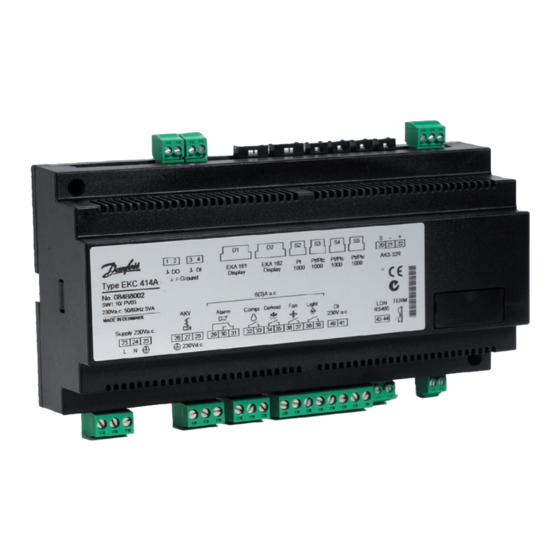
- Page 1 Controller for controlling one evaporator EKC 414A Manual REFRIGERATION AND AIR CONDITIONING...
-
Page 2: Digital Input
The controller is provided with LON RS 485 data communication. Customer display More about this data communication on page 18. If the temperature in the appliance is to be visible to, say, custom- ers, a display can be mounted. Manual RS8CK502 © Danfoss 05-2005 EKC 414A... - Page 3 The controller comes prepared with plug and terminals so that the module just has to be pushed in. Subsequently, up to six defrosts per day can be set. The module has battery back-up. EKC 414A Manual RS8CK502 © Danfoss 05-2005...
-
Page 4: Survey Of Functions
E.g. 5 K, if S4 is the thermostat sensor, or 3 K, if S3 is the thermostat sensor. For modulating thermostats the differential must not be set lower than 5 K. Manual RS8CK502 © Danfoss 05-2005 EKC 414A... - Page 5 To prevent irregular operation, values can be set for the time the compressor is to run once it has been started. And for how long it at least has to be stopped. Min. ON-time (in minutes) Min. On time Min. OFF-time (in minutes) Min. Off time EKC 414A Manual RS8CK502 © Danfoss 05-2005...
-
Page 6: Defrost Control
Def. start Here you can start a manual defrost Hold After Def. Shows ON when the controller is operating with coordinated defrost. Manual RS8CK502 © Danfoss 05-2005 EKC 414A... -
Page 7: Injection Control
The value should only be changed by specially trained staff. Forced closing Inject Close The AKV valve will close when the function is set in pos. ON. (It will also close when the "Inject ON " input is de-energised). EKC 414A Manual RS8CK502 © Danfoss 05-2005... - Page 8 If the settings in the controller are to be protected with an access code you can set a numerical value between 0 and 100. If not, you can cancel the function with setting OFF. Manual RS8CK502 © Danfoss 05-2005 EKC 414A...
- Page 9 1=R12. 2=R22. 3=R134a. 4=R502. 5=R717. 6=R13. 7=R13b1. 8=R23. 9=R500. 10=R503. 11=R114. 12=R142b. 13=Userdefined. 14=R32. 15=R227. 16=R401A. 17=R507. 18=R402A. 19=R404A. 20=R407C. 21=R407A. 22=R407B. 23=R410A. 24=R170. 25=R290. 26=R600. 27=R600a. 28=R744. 29=R1270. 30=R417A Warning: Wrong selection of refrigerant may cause damage to the compressor. EKC 414A Manual RS8CK502 © Danfoss 05-2005...
- Page 10 E-alarms, on the other hand, will become visible the moment the error occurs. (An A alarm will not be visible as long as there is an active E alarm). High temperature alarm High Temp. air Low temperature alarm Low temp. air Manual RS8CK502 © Danfoss 05-2005 EKC 414A...
- Page 11 Start-up phase 2. Evaporator being charged Adaptive control Start-up phase 1. Signal reliability from sensors is controlled Manual control of outputs No refrigerant selected Delay on outputs during start-up Password required. Set password EKC 414A Manual RS8CK502 © Danfoss 05-2005...
- Page 12 Connection Cable length between an external display and EKC 414A must be max. 15 m AKS 32R: 1= Black 2= Blue 3= Brown Coordinated defrost via cable connections Coordinated defrost via data communication Manual RS8CK502 © Danfoss 05-2005 EKC 414A...
- Page 13 23 - 24 Supply voltage 230 V 50/60 Hz 25, 26 Protective earth connection Danfoss wil not be responsible for any goods, or plant compo- 27 - 28 Expansion valve type AKV (230 V d.c.) nents, damaged as a result of the above defects. It is the installer's 40 - 41 230 V signal for start/stop of regulation responsibility to check the installation thoroughly, and to fit the...
-
Page 14: Operation
��������� ��������� ����� ����� ��������� ��������� ����� ������������ ����� ����������� ����� ������ ��� ����� ����� ����� ���������� ��������������� ���������� ����� ������������ ����������� ����������� ������ ����� ����� ��������������� ���� ���������� ����� ����� ��������� ���� Manual RS8CK502 © Danfoss 05-2005 EKC 414A... -
Page 15: Menu Survey
21=R407A. 22=R407B. 23=R410A. 24=R170. staff 25=R290. 26=R600. 27=R600a. 28=R744. Adaptive control 29=R1270. 30=R417A Should only be changed to OFF by trained staff Average opening degree 30.0 Should only be changed by trained staff EKC 414A Manual RS8CK502 © Danfoss 05-2005... - Page 16 Start-up phase 2. Evaporator is charged Adaptive control Start-up phase 1. Signal reliability from the sen- sors is checked Manual control of outputs No refrigerant selected Time delay on outputs during start-up Password required. Set password Manual RS8CK502 © Danfoss 05-2005 EKC 414A...
-
Page 17: Montage
EMC-tested acc. to EN 50081-1 and EN 50082-2 IP 20 AC 15 load acc. to EN 60947-5-1 Only for front mounting (IP 40) Only connection via plugs Display type EKA 161 / 162 EKC 414A Manual RS8CK502 © Danfoss 05-2005... -
Page 18: Data Communication
• If you wish to check earlier text will be retransmitted, but now with status value 0. the parameter names of the temperature measurements, functions on page 4-11. you can see them in the log collection. Manual RS8CK502 © Danfoss 05-2005 EKC 414A... - Page 19 EKC 414A Manual RS8CK502 © Danfoss 05-2005...
- Page 20 Refrigeration controls with EKC LonWorks®. Danfoss can accept no responsibility for possible errors in catalogues, brochures and other printed material. Danfoss reserves the right to alter its products without notice. This also applies to products already on order provided that such alternations can be made without subsequential changes being necessary in specifications already agreed.
Need help?
Do you have a question about the EKC 414A and is the answer not in the manual?
Questions and answers