
Related Manuals for Danfoss EKC 313


Summary of Contents for Danfoss EKC 313
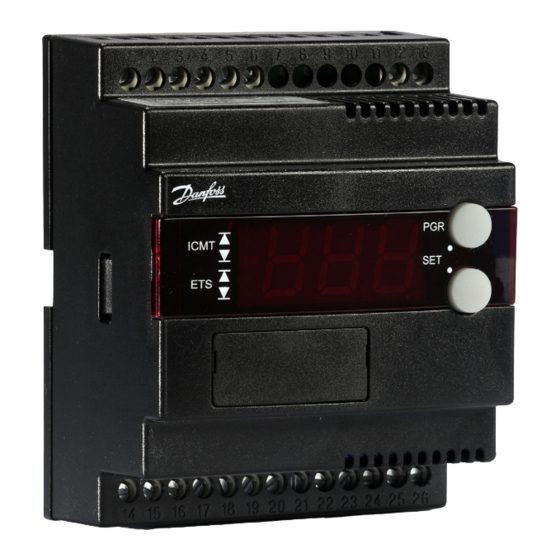
- Page 1 User Guide Controller for cascade systems with CO 2 EKC 313 ADAP-KOOL® Refrigeration control systems...
-
Page 2: Table Of Contents
PC – either on the spot or in a service company. Contents Introduction ....................... 2 Menu survey ....................... 8 Example ....................... 3 Connections .....................10 Function overview ................... 4 Data ........................11 Operation ......................8 Ordering ......................11 User Guide RS8FZ402 © Danfoss 2015-07 EKC 313... -
Page 3: Example
If the condensing pressure falls below the set value, the opti- mised superheat regulation ceases and the ETS valve closes gradually until the pressure rises above the value. EKC 313 User Guide RS8FZ402 © Danfoss 2015-07... -
Page 4: Function Overview
If no MOP function is required, select pos. Off. (A value of max. (60) will correspond to Off ) Min. value for the superheat reference SH Min Max. value for the superheat reference SH Max D: Differentiation time Td Td sec User Guide RS8FZ402 © Danfoss 2015-07 EKC 313... - Page 5 50 / 60 Hz Set the net frequency. (50=0, 60=1) Definition of relay Alarm/Valve The relay can be defined for the following applications: 0: Alarm relay 1: Control of EVR-valve in liquid line. EKC 313 User Guide RS8FZ402 © Danfoss 2015-07...
- Page 6 S10 (off ): Regulation stopped by the internal start/ stop. S24: Regulation is in start-up mode S44: Delay time, or the time it takes for system stability to be reached. Appears if one of the regulating sensors fails. User Guide RS8FZ402 © Danfoss 2015-07 EKC 313...
- Page 7 A11: No refrigerant has been selected. o30 must be set No Rfg. Sel. A43: Step motor fault. Output or phase Step motor err A45: Regulation stopped. Main switch r12 = off Standby mode EKC 313 User Guide RS8FZ402 © Danfoss 2015-07...
-
Page 8: Menu Survey
**) The display on the controller can show 3 digits only, but the setting value has 4 digits. Only the 3 most important will be shown. It means fx. 250 will give a setting of 2500. User Guide RS8FZ402 © Danfoss 2015-07 EKC 313... - Page 9 Read ETS valves opening degree Read pressure at pressure transmitter P0 Read P0 converted to temperature °C Read calculated SH closing value Read Pc converted to temperature °C Read pressure at pressure transmitter Pc EKC 313 User Guide RS8FZ402 © Danfoss 2015-07...
-
Page 10: Connections
It is important that the installation of the data communi- cation cable be done correctly. Cf. separate literature No. RC8AC... *) For explosive applications an intrinsically safe pressure transmitter can be used. Connection is shown on page 12. User Guide RS8FZ402 © Danfoss 2015-07 EKC 313... -
Page 11: Data
Temperature sensor Pt 1000 ohm and pressure transmitter: Kindly refer to catalogue RK0YG EMC acc. EN 61000-6-3 and EN 61000-4-(2-6, 8,11) Approvals LVD acc. EN 60730-1 and EN 60730-2-9 EKC 313 does not support valve type ETS 6. EKC 313 User Guide RS8FZ402 © Danfoss 2015-07... - Page 12 Danfoss can accept no responsibility for possible errors in catalogues, brochures and other printed material. Danfoss reserves the right to alter its products without notice. This also applies to products already on order provided that such alternations can be made without subsequential changes being necessary in specifications already agreed.
Need help?
Do you have a question about the EKC 313 and is the answer not in the manual?
Questions and answers