2N Access Unit M Installation Manual
Hide thumbs
Also See for Access Unit M:
- Installation manual (42 pages) ,
- User manual (50 pages) ,
- Installation manual (67 pages)
Table of Contents
Advertisement
Advertisement
Table of Contents

Related Manuals for 2N Access Unit M


Summary of Contents for 2N Access Unit M
- Page 1 Access Unit M Access Control Installation manual Version: www.2n.cz...
- Page 2 2N TELEKOMUNIKACE a.s. administers the FAQ database to help you quickly find information and to answer your questions about 2N products and services. On www. faq.2n.cz you can find information regarding products adjustment and instructions for optimum use and procedures „What to do if...".
-
Page 3: Table Of Contents
2. Description of Installation 2.1 Before You Start 2.2 Mechanical Installation 2.3 Electric Installation 2.4 Extending Module Connection 3. Detection of 2N Access Unit M using 2N® Network Scanner 4. Factory Reset 5. Maintenance 6. Status Signaling 7. Technical Parameters 7.1 General Drawings... -
Page 4: Product Overview
1. Product Overview Here is what you can find in this section: 1.1 Components and Associated Products 1.2 Terms and Symbols 2N TELEKOMUNIKACE a.s., www.2n.cz 4/56... - Page 5 Basic Features 2N Access Unit M is an elegant and reliable access IP system equipped with a number of useful functions. 2N Access Unit M is a single-module access system available in several versions. All the 2N Access Unit M versions include an integrated card reader module which helps control access using an RFID card.
- Page 6 LAN (PoE) or external 12V power supply Configuration using web interface HTTP server for API configuration SNTP client for time synchronization SMTP client for email sending, Picture to Email feature TFTP/HTTP client for automated firmware and configuration upgrade and update 2N TELEKOMUNIKACE a.s., www.2n.cz 6/56...
-
Page 7: Components And Associated Products
Mobile Key Part No. 916112-S ® Access Unit M secured 13.56 MHz, NFC ready is used for reading secured RFID cards in the 13.56 MHz bandwidth with the NFC support. Combining an access reader and a controller, the device is used for access control inside and outside of buildings. - Page 8 Mobile Key Part No. 916114-S ® Access Unit M RFID 125 kHz, secured 13.56 MHz, NFC is used for reading RFID cards in the 125 kHz bandwidth and secured cards in the 13.56 MHz bandwidth with the NFC support. Combining an access reader and a controller, the device is used for access control inside and outside of buildings.
- Page 9 Main Units Part No. 916115 ® Access Unit M Bluetooth & RFID 125 kHz, 13.56 MHz, NFC is used for reading RFID cards in the 125 kHz and 13.56 MHz bandwidths with the NFC support. Combining an access reader, a Bluetooth module and a controller, the device is used for access control inside and outside of buildings.
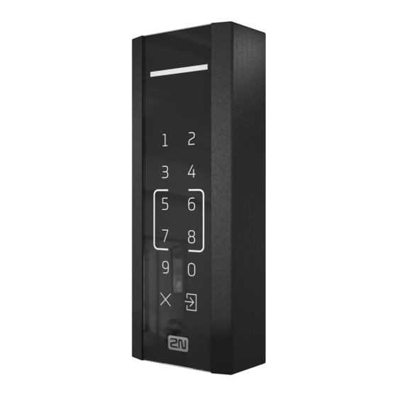
- Page 10 Main Units Part No. 916116 ® Access Unit M Touch Keypad & RFID 125 kHz, 13.56 MHz, NFC is used for reading RFID cards in the 125 kHz and 13.56 MHz bandwidths with the NFC support. Combining an access reader, a touch keypad and a controller, the device is used for access control inside and outside of buildings.
- Page 11 License Part No. 9160401 2N Access Unit Lift module license Electric Locks Part No. 932071E BEFO 11211 12 V / 230 mA DC low consumption Part No. 932081E BEFO 11221 with momentum pin 12 V / 230 mA DC low consumption A very short electric pulse is enough to put the lock in the OPEN position and unlock the door.
- Page 12 The reverse lock is closed when electricity is switched on. When electricity is interrupted, the lock is opened. It contains a built-in contact to indicate whether the door is open or closed. FAQ: Electric locks – Differences between locks for 2N IP access systems 2N TELEKOMUNIKACE a.s., www.2n.cz 12/56...
- Page 13 12 V / 1 A adapter 91341482E A stabilized power supply needs to be used where no PoE is available. 91341482US Part No. 932928 12 V transformer for electric lock Additional Modules Part No. 9159010 Security Relay 2N TELEKOMUNIKACE a.s., www.2n.cz 13/56...
- Page 14 Part No. 9134173 RFID card, Mifare Classic 1k, 13.56 MHz Part No. 9134174 RFID fob, Mifare Classic 1k, 13.56 MHz 2N TELEKOMUNIKACE a.s., www.2n.cz 14/56...
- Page 15 External RFID card reader connectable to a PC via a USB interface. Suitable for system administration and adding of ® EM41xx cards (125 kHz) via a web interface or 2N Access Commander Part No. 9137421E USB Reader of 13.56 MHz, 125 kHz RFID Cards and...
- Page 16 Mobile Key required) EMarine Part No. 9137410E External IP relay – 1 output A stand-alone IP device, which can be controlled from an IP intercom via HTTP commands, which can thus control devices on unlimited distance. 2N TELEKOMUNIKACE a.s., www.2n.cz 16/56...
- Page 17 IP end devices connected. Part No. 9160501 AXIS A9188 Network I/O relay module Lift control relay module for up to 8 floors 2N TELEKOMUNIKACE a.s., www.2n.cz 17/56...
- Page 18 Refer to the local 2N distributor for more accessories and recommendations please. 2N TELEKOMUNIKACE a.s., www.2n.cz 18/56...
-
Page 19: Terms And Symbols
Warning Always abide by this information to prevent damage to the device. Caution Important information for system functionality. Useful information for quick and efficient functionality. Note Routines or advice for efficient use of the device. 2N TELEKOMUNIKACE a.s., www.2n.cz 19/56... -
Page 20: Description Of Installation
2. Description of Installation Here is what you can find in this section: 2.1 Before You Start 2.2 Mechanical Installation 2.3 Electric Installation 2.4 Extending Module Connection 2N TELEKOMUNIKACE a.s., www.2n.cz 20/56... -
Page 21: Before You Start
2.1 Before You Start Before starting the installation, please check whether your 2N Access Unit M package complies with the following list. Package complies with the following list. 2N Access Unit M Wall holder (screwed to the device) 8 mm dowel... -
Page 22: Mechanical Installation
2.2 Mechanical Installation 2N Access Unit M is designed for surface mounting (wall, plasterboard, door frames). Use the drilling template shown on the device box to prepare holes of the required sizes for cabling and dowels on the selected place in the required height. Feed the cables out of the pre-predrilled hole. - Page 23 Then fit the holder through the dedicated holes using the screws enclosed. Interconnect the fed-out cables with the 2N Access Unit M cabling. Put the device carefully on the installed holder from above downwards and fix its position on the holder carrying elements by tightening the screw from the bottom through the holder hole.
-
Page 24: Electric Installation
2.3 Electric Installation 2N Access Unit M can be fed either from an external 12 V / 1 A DC power supply or from a PoE 802.3af supporting LAN. External power supply Use a 12 V ± 15 % SELV supply dimensioned to the current consumption required for the access unit power output to make your device work reliably. - Page 25 Caution We recommend the use of a LAN surge protection. We recommend the use of a shielded SSTP Ethernet cable. 2N TELEKOMUNIKACE a.s., www.2n.cz 25/56...
- Page 26 0.14 0.14 0.14 W 0.14 0.14 0.14 W 0.14 0.14 W temperature mode OUT1 at maximum possible load Audio 0.7 W 0.7 W 0.7 W 0.7 W 0.7 W 0.7 W 0.7 W 0.7 W 2N TELEKOMUNIKACE a.s., www.2n.cz 26/56...
- Page 27 Description of 2N Access Unit M Cabling Legend Relay Relay cable with a 30 V / 1 A AC/DC NO/NC contact Input 1, An input cable used for the connection of a departure button, open door sensor, ESS etc. in the passive/active mode (−30 V to +30 V DC).
- Page 28 RESET / FACTORY RESET button. button All the available cables are 35 cm long. Wiring diagram for Relay cables The electric lock is unlocked whenever power is supplied The magnetic lock is unlocked whenever the power supply is disconnected 2N TELEKOMUNIKACE a.s., www.2n.cz 28/56...
- Page 29 Wiring Diagram for IN1, IN2 Wires in Passive Mode Security The 12 V output is used for lock connection. If, however, the unit (2N IP Intercom, 2N Access Unit) is installed where unauthorized tampering may happen (building envelopes), we strongly recommend that Security Relay (Part No.
- Page 30 For this way of protection we recommend a diode 1 A / 1000 V (e.g., 1N4007, 1N5407, 1N5408) connected antiparallel to the device. 2N TELEKOMUNIKACE a.s., www.2n.cz 30/56...
-
Page 31: Extending Module Connection
Security Relay Part No. 9159010 ) is used for enhancing security between the access unit and the connected electric lock. It significantly enhances security of the connected electric lock as it prevents unlocking by forced opening of 2N Access Unit Function: Security Relay is a device installed between the access unit (outside the secured area) and an electric lock (inside the secured area). - Page 32 To the passive output in series with an external power supply. The device also supports a Departure button connected between the ‘PB’ and – Helios /2N IP intercom’ terminals. Press the Departure button to activate the output for 5 seconds.
- Page 33 2.18 or higher, it is necessary to reprogram Security Relay using the instructions above. FAQ: 2N® Security Relay – description of the device and use with the 2N IP intercoms Video Tutorial: 2N IP Door Intercoms – Security Relay Connection: 2N TELEKOMUNIKACE a.s., www.2n.cz...
-
Page 34: Detection Of 2N Access Unit M Using 2N® Network Scanner
3. Detection of 2N Access Unit M using 2N® Network Scanner 2N Access Unit M is configured via the administration web server. Connect the device to the LAN IP and make sure it is properly powered. 2N TELEKOMUNIKACE a.s., www.2n.cz... - Page 35 The application helps you find the IP addresses of all the 2N Access Unit M devices in the LAN. Download the app from the 2N web sites ( www.2n.cz ). Make sure that Microsoft .NET Framework 2.0 is installed for successful app installation.
- Page 36 IP address or activate DHCP. The default configuration password is 2n. If the found device is grey highlighted, its IP address cannot be configured using this application. In that case, click Refresh to find the device again and check whether multicast is enabled in your network.
- Page 37 ® IP Network Scanner IP Address Change 2N TELEKOMUNIKACE a.s., www.2n.cz 37/56...
-
Page 38: Factory Reset
Press the button shortly (< 1 s) to restart the system without changing configuration. Note 2N Access Unit M time interval between the short press of the RESET button and reconnection of the device to the network is 26 s. - Page 39 The device announces the current IP address via the speaker automatically. Note The delay between the RESET button press and the first light and sound signaling is 15–35 s depending on the 2N Access Unit model used. 2N Access Unit M the time interval is 14 s.
- Page 40 Wait until the red LED goes off and the acoustic signal can be heard (approx. for another 3 s). Release the RESET button. The following network parameters will be set after restart: IP address: 192.168.1.100 Network mask: 255.255.255.0 Default gateway: 192.168.1.1 2N TELEKOMUNIKACE a.s., www.2n.cz 40/56...
- Page 41 (approx. for another 3 s). Wait until the green LED goes off and the red LED goes on again and the acoustic signal can be heard (approx. for another 3 s). Release the RESET button. 2N TELEKOMUNIKACE a.s., www.2n.cz 41/56...
- Page 42 Release the RESET button. Caution In case the factory default values are reset on the device with a firmware version 2.18 or higher, it is necessary to reprogram Security Relay using the instructions from Subsection 2.4 Extending ModuleConnection 2N TELEKOMUNIKACE a.s., www.2n.cz 42/56...
-
Page 43: Maintenance
Do not use aggressive detergents (such as abrasives or strong disinfectants). Clean the device in dry weather in order to make waste water evaporate quickly. Warning Prevent water from getting inside the access unit. Do not use alcohol-based cleaners. 2N TELEKOMUNIKACE a.s., www.2n.cz 43/56... -
Page 44: Status Signaling
The light signal can be accompanied with an acoustic signal if set so. Refer to 5.3.3 Audio of the 2N Access Unit Configuration Manual for the setting options. The white LED light indicates the power supply and operation states. - Page 45 RFID card is applied. Subsequently, the set switch is not activated. An invalid authentication is indicated by an acoustic signal if set so. Set the LED backlight level in the Hardware/Backlight section, refer to 5.3.4 Backlight of the Configuration Manual for more details. 2N TELEKOMUNIKACE a.s., www.2n.cz 45/56...
-
Page 46: Technical Parameters
8 to 12 V DC according to power supply (PoE: 10 V; adapter: supply voltage minus 2 V), up to 400 mA Tamper switch: part of 2N Access Unit M Inputs (Input 1,2): passive/active mode (−30 V to +30 V DC) OFF = open or U > 1.5 V ON = short-circuited or U <... - Page 47 Working relative humidity: 10 % – 95 % (non-condensing) Maximum altitude for intended use: 2000 m a.s.l. Storage temperature: −40 °C to 70 °C Dimensions: 132 (H) x 50 (W) x 27 (D) [mm] Weight: 460 g Covering level: IP55 2N TELEKOMUNIKACE a.s., www.2n.cz 47/56...
-
Page 48: General Drawings
7.1 General Drawings 2N TELEKOMUNIKACE a.s., www.2n.cz 48/56... - Page 49 2N TELEKOMUNIKACE a.s., www.2n.cz 49/56...
-
Page 50: Supplementary Information
8. Supplementary Information 8.1 General Instructions and Cautions 8.2 Troubleshooting 8.3 Directives, Laws and Regulations 2N TELEKOMUNIKACE a.s., www.2n.cz 50/56... -
Page 51: General Instructions And Cautions
The consumer shall, at its own expense, obtain software protection of the product. The manufacturer shall not be held liable and responsible for any damage incurred as a result of the use of deficient or substandard security software. 2N TELEKOMUNIKACE a.s., www.2n.cz 51/56... - Page 52 Make sure that the devices to be disposed of are complete. Do not throw battery packs into fire. Battery packs may not be taken into parts or short-circuited either. 2N TELEKOMUNIKACE a.s., www.2n.cz 52/56...
-
Page 53: Troubleshooting
8.2 Troubleshooting For the most frequently asked questions refer to faq.2n.cz 2N TELEKOMUNIKACE a.s., www.2n.cz 53/56... -
Page 54: Directives, Laws And Regulations
8.3 Directives, Laws and Regulations ® Access Unit M conforms to the following directives and regulations: 2014/53/EU for radio equipment 2011/65/EU on the restriction of the use of certain hazardous substances in electrical and electronic equipment 2012/19/EU on waste electrical and electronic equipment Industry Canada This Class A digital apparatus complies with Canadian ICES-003/NMB-003. - Page 55 2N TELEKOMUNIKACE a.s. is not liable neither for any limitation of such a product’s functionality, nor for any damage, loss or injury relating to such a potential limitation of functionality.
- Page 56 2N TELEKOMUNIKACE a.s. Modřanská 621, 143 01 Prague 4, Czech Republic Phone: +420 261 301 500, Fax: +420 261 301 599 E-mail: sales@2n.cz Web: www.2n.cz v1.0 2N TELEKOMUNIKACE a.s., www.2n.cz 56/56...
Need help?
Do you have a question about the Access Unit M and is the answer not in the manual?
Questions and answers