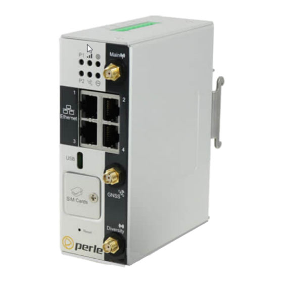
Perle IRG5140+ Hardware Installation Manual
Hide thumbs
Also See for IRG5140+:
- Hardware installation manual (35 pages) ,
- Quick start manual (3 pages) ,
- Hardware installation manual (32 pages)

Related Manuals for Perle IRG5140+


Summary of Contents for Perle IRG5140+
- Page 1 Perle IRG5140+ Router Hardware Installation Guide Updated June 2021 Version A.06.03.2021 Document Part# 5500456-10 www.perle.com...
-
Page 2: Preface
Routers. It covers hardware features as well as installation and operation. This document does not cover how to configure your Perle IRG 5140 router. Information to configure your Perle router can be found in the Perle IRG5000 Series Router User’s Guide and the Perle IRG5000 Series Router CLI Reference Guide on the Perle website. - Page 3 Perle IRG5000 Series Router CLI Command Line Interface Reference Guide using CLI Reference Guide commands to configure the IRG 5140 (this is an advanced way to configure the router). Perle IRG5140+ Series Router Hardware Installation Guide...
- Page 4 Perle IRG 5140 series router even if Perle has been advised or the possibility of such damages or they are foreseeable or for claims by any third party.
- Page 5 Cet équipement doit être utilisé dans les matières spécifiées par le fabricant. Warning: In case of malfunction or damage, no attempts at repair should be made by the user. Do not dismantle this product. In case of malfunction or damage, contact Perle Technical support at https://www.perle.com/support_services/support_request.aspx or email at https://www.perle.com/support_services/support_request.aspx#form...
- Page 6 Avertissement: DANGER D'EXPLOSION ET D'AVERTISSEMENT - Ne pas connecter ou decon- necter l'équipement tant que l'alimentation n'est pas débranchée ou que la zone n'est pas dangereuse. Perle IRG5140+ Series Router Hardware Installation Guide...
- Page 7 être altérée. Warning: In case of malfunction or damage, no attempts at repair should be made. Do not dismantle the product. All repairs need to be made by a qualified Perle representative. Contact Perle Systems Technical support at or email at https://www.perle.com/support_services/support_request.aspx...
- Page 8 Modifications to this product not authorized by Perle could void the FCC approval and negate your authority to operate the product.
- Page 9 Publishing History Date Revision Update Details March 2020 A.03.23.2020 Initial release. Dec 2020 A.12.31.2020 Updates to LED tables. April 2021 A.04.26.2021 Update to Factory default table June 2021 A.06.03.2021 Update to label Perle IRG5140+ Series Router Hardware Installation Guide VIII...
-
Page 10: Table Of Contents
Table Of Contents Preface ............. . . I Overview . -
Page 11: Overview
• Providing reliable Internet access to a mobile workforce What’s Included The following components may be included with your product. Components will vary depending for each model. See the Perle website for updates. • The router • Quick Start Guide •... -
Page 12: Hardware
Low Power Meaning Mode (P1 and P2) Power must be applied to the Power inputs P1 and P2 in order for the LEDs to light. No Power Boot Red—solid Green— Blip Powering up Amber—flashing Perle IRG5140+ Series Router Hardware Installation Guide... - Page 13 No Config Green—flashing Unit is powered up normally—unit has no config. Unit is in Safe mode or Factory default mode. Function Normal Low Power Meaning WWAN Mode Disabled Perle IRG5140+ Series Router Hardware Installation Guide...
- Page 14 Function Normal Low Power Meaning Mode No VPN No VPN configured or enabled. Green—solid VPN established—at established least 1 VPN connection is up. VPN Failed Red—solid Red—blip Internet is up, but VPN failed Perle IRG5140+ Series Router Hardware Installation Guide...
- Page 15 insufficient signal no service modem failure data connection failed—waiting to retry PIN incorrect SIM blocked, bad unlock code SIM locked SIM blocked, unblock code incorrect Perle IRG5140+ Series Router Hardware Installation Guide...
-
Page 16: Sim Card/S
(CLI) as well as provides statuses, logging, and troubleshooting information. Alternative, this port can be set as an Ethernet over USB port. Connecting to the USB-C port in Console Mode Connecting to the USB-C port as an Ether- net over USB Port. Perle IRG5140+ Series Router Hardware Installation Guide... -
Page 17: Ethernet Lan Ports
Link + Flashing with activity 100 Mbps Right LED Green Link + Flashing with activity 10 Mbps No LAN connected GNSS Connector GPS+GLONAS+GAILEO Passive Antenna—SMA(M) straight connector GNSS Technical Specifications for electrical details. Perle IRG5140+ Series Router Hardware Installation Guide... -
Page 18: Terminal Block-Power Connector
SIM card if your network setup requires it. 3. Align the SIM cover plate and secure the plate with the screw. IRG5140+ router Do not force the SIM(s) card in or you may damage the card or your Note: Perle IRG5140+ Series Router Hardware Installation Guide... -
Page 19: Connecting The Antenna/S
(UTP) cables of up to 100 meters (328ft) in length. Cat5e or Cat6 cables are recommended for 1000 Mbps connections. Female Serial Pin out Name Description Type Data Carrier Detect Transmit Data Receive Data Perle IRG5140+ Series Router Hardware Installation Guide... -
Page 20: Connecting To The Usb-C Port In Console Mode
In this mode, the USB-C port behaves as if a PC is connected to the Ethernet port, allowing access to networks and the Internet. See the Perle IRG5000 Series Router User’s Guide and the Perle IRG5000 Series Router CLI Refer- ence Guide for more information on setting this parameter. -
Page 21: Connecting The Power
Cable and connector must be rated for minimum 76°C (168.8°F) Before servicing this product ensure the power source has been disconnected. Electrical Note: installations should be performed by personnel thoroughly trained in safe electrical wiring procedures. Perle IRG5140+ Series Router Hardware Installation Guide... -
Page 22: Operation
Safe Mode Press the Reset button All LEDs, except Saves the startup config while powering up Power blinking Boots with no config file Amber Allows you to do setup mode Perle IRG5140+ Series Router Hardware Installation Guide... -
Page 23: Fast Setup
Fast Setup mode allows you to quickly configure basic operating parameters on your router. Your Perle router is shipped to you in Factory Default mode. On power up, your router is in “Fast Setup” mode with the Power LED flashing green. Make a connection to your router via the console port or a Web browser, then answer basic setup operating parameters such as your initial user ID and password. -
Page 24: Managing The Irg5140
Perle Managed Media Converters, Ethernet Copper Extenders, Industrial Switches, IRG Series of Perle Routers and other Perle products. Your Internet browser can securely access PerleVIEW and manage 10’s, 100’s or 1000’s of Perle devices from a centralized server. -
Page 25: I/O Configurations
Pins 5 and 6 of the power connector can be connected to an external circuit which will be controlled by the internal relay. When the relay is engaged, the external circuit will be completed. The relay is a Normally Open (NO) relay. The relay is rated at a maximum of 1A@24VDC Perle IRG5140+ Series Router Hardware Installation Guide... -
Page 26: Appendix A-Technical Specifications
Storage Humidity Ranges 0% to 95% non-condensing Operating Altitude Up to 3,048 meters (10,000 feet) MTBF 287,215 hours Standards and Certifications Safety UL/ULC/EN 62368-1 (previously 60950-1) CE Mark CAN/CSA-C22.2 No. 62368-1-14 UL 61010-1 and 61010-2-201 Perle IRG5140+ Series Router Hardware Installation Guide... - Page 27 Complaint to IP64 Drop ISTA 2A 2001, test categorizes 1, 4,5, and 6 Power connector Digital input and pulse counting Digital Input & Pulse Counting VDC: 0 for ≤ 1V, 1 for ≥ 2.7 Perle IRG5140+ Series Router Hardware Installation Guide...
- Page 28 1800 Band 4 1700 Band 5 Band 7 2600 Band 8 Band 9 1800 Band 12 Band 13 Band 18 Band 19 Band 20 Band 26 Band 28 Band 29 Band 30 2300 Perle IRG5140+ Series Router Hardware Installation Guide...
- Page 29 Operating Bands - 704-902-928-960 MHz Frequency range 1427.9-1575.42 MHz 1710-2170 MHz 2400-2480-2690 MHz Impedance 50 OHM Gain 2-3 dBi VSWR of Ant 1 and Ant 2 < 3.0 On all bands including Band edges. Perle IRG5140+ Series Router Hardware Installation Guide...
-
Page 30: Appendix B-Sample Labels
Appendix B—Sample Labels Perle IRG5140+ Series Router Hardware Installation Guide... -
Page 31: Appendix C-Mounting The Router
2. Insert a flat blade screwdriver into the slot and twist the base to release the clip. Alternatively a downward force on the clip releases the clip. 3. When the clip is released, pull the bottom of the router out slightly and remove it from the DIN Rail. Perle IRG5140+ Series Router Hardware Installation Guide... -
Page 32: Appendix D-Mechanical
Appendix D—Mechanical Perle IRG5140+ Series Router Hardware Installation Guide... -
Page 33: Appendix E-Maintaining And Troubleshooting
• Ensure cables are not bent, constricted, close to high amperages, or exposed to extreme temperatures • Check that the front panel LEDs are easily visible • Wipe case clean with a dry cloth—do not use solvents or cleaning agents Perle IRG5140+ Series Router Hardware Installation Guide...
Need help?
Do you have a question about the IRG5140+ and is the answer not in the manual?
Questions and answers