
Subscribe to Our Youtube Channel
Related Manuals for Perle IRG5541


Summary of Contents for Perle IRG5541
- Page 1 Perle IRG5541+ FN Router Hardware Installation Guide Updated May 2021 Version A.05.05.2021 Document Part#5500473-10 www.perle.com...
-
Page 2: Preface
This document does not cover how to configure your Perle 5541+ FN router. Information to configure your router can be found in the Perle IRG5000 Series Router User’s Guide and the Perle IRG5000 Series Router CLI Reference Guide located on the Perle website. - Page 3 Data may be delayed, corrupted (i.e., have errors) or be totally lost. Although significant delays or losses of data are rare when cellular devices such as the Perle IRG5541+ FN router is used in a normal manner with a well-constructed network. The Perle IRG5541+ FN router should not be used in situations where failure to transmit or receive data could result in damage of any kind to the user or any other party, including but not limited to personal injury, death, or loss of property.
- Page 4 Notwithstanding the foregoing, in no event shall Perle aggregate liability arising under or in connection with the Perle product, regardless of the number of events, occurrences, or claims giv- ing rise to liability, be in excess of the price paid by the purchaser for the Perle product.
- Page 5 IRG5541+ FN router as indicated on the product label. Avertissement: Assurez-vous que les valeurs nominales de tension et de courant de la source d'ali- mentation prévue conviennent aux routeurs de la série IRG5541+ FN, comme indiqué sur l'étiquette du produit. Warning: Ensure that the installation and electrical wiring of the equipment is performed by trained and qualified personnel and that the installation complies with all local and national electrical codes.
- Page 6 IEC/EN 60079-0 and accessible only by the use of a tool. Les modèles de routeurs IRG5541+ FN sont destinés à être installés dans un boîtier certifié IECEx/ATEX qui conforme à la norme IP54 conformément à la norme IEC/EN 60079-0 et accessible uniquement à...
- Page 7 être altérée. Warning: In case of malfunction or damage, no attempts at repair should be made. Do not dismantle the product. All repairs need to be made by a qualified Perle representative. Contact Perle Systems Technical support at or email at https://www.perle.com/support_services/support_request.aspx...
- Page 8 Modifications to this product not authorized by Perle could void the FCC approval and negate your authority to operate the product.
- Page 9 Preface Publishing History Date Revision Update Details May 2021 A.03.05.2021 Initial release. Perle IRG5541+ FN Router Hardware Installation Guide VIII...
-
Page 10: Table Of Contents
Table Of Contents Preface ............. . . I Overview . - Page 11 Pulse Counter / Digital Input ......... . . 20 High Side Pull-up / Dry Contact Switch Input.
-
Page 12: Overview
Ethernet port. It supports LTE/4G wireless solutions for both fixed and mobile applications (IoT). The IRG5541+ FN LTE/4G router supports Cat-12 tech- nology with peak download rates of 600 Mbps and uploads speeds of 150 Mbps. It offers global cov- erage of frequency bands, supports Cat-12 technology with automatic fall-back to 3G (HSPA+,UMTS) networks, and is FirstNet Ready™. -
Page 13: Hardware
Normal Low Power Meaning Mode No Power Boot Red—solid Green—Blip Powering up Amber—flashing Normal Green—solid Green—blip Operation starting after a boot is complete Normal Green—flashing operation but no config Fatal error Red—solid Red—solid Perle IRG5541+ FN Router Hardware Installation Guide... - Page 14 Mode or Factory default Mode. Function Normal Low Power Meaning Serial Mode Disabled or not Always off in power in use saving mode. Serial port/s Green—flashing TX/RX WWAN Function Normal Low Power Meaning Mode Disabled Perle IRG5541+ FN Router Hardware Installation Guide...
- Page 15 Function Normal Low Power Meaning Mode 5.0GHz Green—solid Client mode connected—AP Radio mode. 5.0 TX/RX Green—flashing Client or AP activity. 2.4GHz Amber—solid Client mode connected—AP-radio active. 2.4 TX/RX Amber—flashing Client or AP activity. Perle IRG5541+ FN Router Hardware Installation Guide...
- Page 16 insufficient signal no service modem failure data connection failed—waiting to retry PIN incorrect SIM blocked, bad unlock code SIM locked SIM blocked, unblock code incorrect Perle IRG5541+ FN Router Hardware Installation Guide...
-
Page 17: Sim Card/S
Alternatively, this port can be set as an Ethernet over USB port. Connecting to the USB-C port in Console Mode Connecting to the USB-C port as an Ether- net over USB Port. Perle IRG5541+ FN Router Hardware Installation Guide... -
Page 18: Ethernet Lan Ports
Pin 3—IGN can be configured as vehicle ignition sense or as analog input. Warning: Before servicing this product ensure the power source has been disconnected. Note: Use copper conductors only. Perle IRG5541+ FN Router Hardware Installation Guide... -
Page 19: Aux /Io
Relay NO (normally open) Pin Number Pin Descriptions RS485 + Input A Relay NO (normally open) Warning: Before connecting wiring, ensure the power source has been disconnected. For application examples see --> AUX I/O Perle IRG5541+ FN Router Hardware Installation Guide... -
Page 20: Relay Alarm
SIM card if your network setup requires it. 3. Align the SIM cover plate and secure the plate with the screws. IRG554x router Note: Do not force the SIM(s) card in or you may damage the card or your Perle IRG5541+ FN Router Hardware Installation Guide... -
Page 21: Connecting The Antenna/S
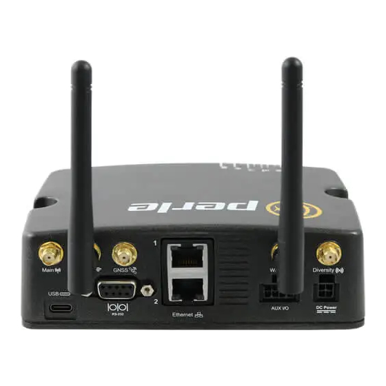
The serial port has a 9-pin female port connector allowing you to directly connect to most computers or devices with a standard serial straight-through cable. It is used for: • Connecting a serial device • Connecting as a console port • As a GNSS output device Perle IRG5541+ FN Router Hardware Installation Guide... -
Page 22: Connecting To The Usb-C Port In Console Mode
PC. 6. Press the Enter key on the keyboard and the prompt displays. See the Perle IRG5000 Series Router CLI Reference Guide for more information on using CLI commands. Warning: If you connect or disconnect the console cable with the power applied to the router or any device on the network, an electrical arc can occur. -
Page 23: Connecting To The Usb-C Port As An Ethernet Over Usb Port
In this mode, the USB-C port behaves as if a PC is connected to the Ethernet port, allowing access to networks and the Internet. See the Perle IRG5000 Series Router User’s Guide and the Perle IRG5000 Series Router CLI Refer- ence Guide for more information on setting this parameter. -
Page 24: Fast Setup
Fast Setup mode allow you to quickly configure basic operating parameters on your router. Your Perle router is shipped to you in Factory Default mode. On power up, your router is in “Fast Setup” mode with the Power LED flashing green. Make a connection to your router via the console port or a Web browser, then answer basic setup operating parameters such as your initial user ID and password. -
Page 25: Cli
A text-based Command Line Interface based on industry standard syntax and structure. The CLI can be accessed from the console port. Once a valid IP address is configured on the IRG5541 + FN, you can Telnet or SSH to access the IRG5541+ FN for administration purposes. See the Perle IRG5000 Series Router CLI Reference Guide for more information. -
Page 26: Power Management
Power Management Power Management Power Modes The IRG5541+ FN has three operating power modes: • Standard Mode • Ignition Mode • Smart Standby Mode Standard Mode When power is applied to the router, it powers up. Both GPIO and IGN power inputs are ignored. -
Page 27: Power Saving Options
Typical Mode setup • Cellular connected • Ethernet connected • Wi-Fi active • Serial disable • USB enabled • GPS enabled—active antenna • CPU power savings mode disabled • LED power savings mode disabled Perle 5541+ FNRouter Hardware Installation Guide... -
Page 28: Low Voltage Standby
Ignition Mode and Smart Standby Mode. The feature can measure voltage either with the IGN pin or the GPIO (analog) pin. See the Perle IRG5000 Series Router User’s Guide on how to configure this feature. -
Page 29: Deployment Modes
• Pin 2 (Ground)—Use the Black wire in the DC cable to connect Pin 2 to Ground • Pin 3 (IGN—Ignition)—It is recommended to use the IGN wire (Pin 3) to initiate standby mode on the router. Perle IRG5541+ FN Router Hardware Installation Guide... -
Page 30: Fixed Installation With Analog Input
• Pin 4 (GPIO)—In this example, the GPIO (green) is used as an analog input to enter and exit Standby Mode For more information on configuring Standby Mode, Timed Standby Mode and Event Handing see the Perle IRG5000 Series Router User’s Guide. Perle IRG5541+ FN Router Hardware Installation Guide... -
Page 31: I/O Configurations
The voltage on Pin 4 when the high side pull-up is enabled (depends on the Vin and power consumption. Minimum Typical Maximum Units Source Current = 12 V = 36 V = 7 V Perle IRG5541+ FN Router Hardware Installation Guide... -
Page 32: Digital Output / Low Side Current Sink
Digital Output / Low Side Current Sink Use Pin 4—GPIO as a low side current sink. State Minimum Typical Maximum Comments 200mA 850mA I_Typical = 25°C I_Min = 70°C I_Max = -40°C ––– ––– Perle IRG5541+ FN Router Hardware Installation Guide... -
Page 33: Digital Output / Open Drain
Pin Descriptions RS485 - Input B Relay NO (normally open) Pin Numbers Pin Descriptions RS485 + Input A Relay NO (normally open) Warning: Before connecting wiring, ensure the power source has been disconnected. Perle IRG5541+ FN Router Hardware Installation Guide... -
Page 34: Pulse Counter / Digital Input
The voltage on Pin 6 or Pin 2 when the high side pull-up is enabled (depends on the Vin and power consumption). *Depending on the load, this value can range from Vin to Vin -2.5 Minimum Typical Maximum Units Source Current = 12 V = 36 V = 7 V -2.5 ––– Perle IRG5541+ FN Router Hardware Installation Guide... -
Page 35: Relay Alarm
AUX I/O Relay Alarm normally open (NO) dry contact 1A@24VDC Perle IRG5541+ FN Router Hardware Installation Guide... -
Page 36: Appendix A-Technical Specifications
Storage Humidity Ranges 0% to 95% non-condensing Operating Altitude Up to 3,048 meters (10,000 feet) MTBF 287,215 hours Standards and Certifications Safety UL/ULC/EN 62368-1 (previously 60950-1) CE Mark CAN/CSA-C22.2 No. 62368-1-14 UL 61010-1 and 61010-2-201 Perle IRG5541+ FN Router Hardware Installation Guide... - Page 37 EN 61373 IP rating Complaint to IP64 Drop ISTA 2A 2001, test categorizes 1, 4,5, and 6 Power connector/AUX Ignition Sense VDC voltage variation with on/Off and scheduling timer Analog Input: 0.5V to 36V Perle IRG5541+ FN Router Hardware Installation Guide...
- Page 38 45 MHz Impedance 50 Ohm VSWR 2.0 Typical Gain RHCP Polarization 4 dBic (typical) Axial Ratio at elevation 5 dB (typical) Cellular Cellular/Telecom Regulatory FCC/ICES, RED, PTCRB/CTIA, CE Approvals Carrier Certifications AT&T, Verizon Perle IRG5541+ FN Router Hardware Installation Guide...
- Page 39 Band 8 Band 9 Band 19 1700 Cellular EN 301 908-1, EN 301- 908-2, EN 301 908-13 EN 62311:2019 / IEC 62311 Ed. 1.0 b:2007 EN 301 489-1 EN 301 489-17 EN 301 489-19 Perle IRG5541+ FN Router Hardware Installation Guide...
- Page 40 Operating Bands - 704-902-928-960 MHz Frequency range 1427.9-1575.42 MHz 1710-2170 MHz 2400-2480-2690 MHz Impedance 50 OHM Gain 2-3 dBi VSWR of Ant 1 and Ant 2 < 3.0 On all bands including Band edges. Perle IRG5541+ FN Router Hardware Installation Guide...
-
Page 41: Appendix B-Sample Label
Appendix B—Sample Label Perle IRG5541+ FN Router Hardware Installation Guide... -
Page 42: Appendix C-Mounting The Router
3. Position the router such that the top hooks of the DIN Rail clip attach into the top of the DIN Rail. 4. Rotate the bottom of the router towards the rail. This will snap the bottom hooks of the Din Rail clip onto the bottom of the DIN Rail. Perle IRG5541+ FN Router Hardware Installation Guide... - Page 43 3. Position the router such that the top hooks of the DIN Rail clip attach onto the top of the DIN Rail. 4. Rotate the bottom of the router towards the rail. This will snap the bottom hooks of the DIN Rail clip into the bottom of the DIN Rail. Perle IRG5541+ FN Router Hardware Installation Guide...
-
Page 44: Appendix D-Mechanical
Appendix D—Mechanical Perle IRG5541+ FN Router Hardware Installation Guide... -
Page 45: Appendix E-Maintaining And Troubleshooting
• Ensure cables are not bent, constricted, close to high amperages, or exposed to extreme temperatures • Check that the front panel LEDs are easily visible • Wipe case clean with a dry cloth—do not use solvents or cleaning agents Perle IRG5541+ FN Router Hardware Installation Guide...
Need help?
Do you have a question about the IRG5541 and is the answer not in the manual?
Questions and answers