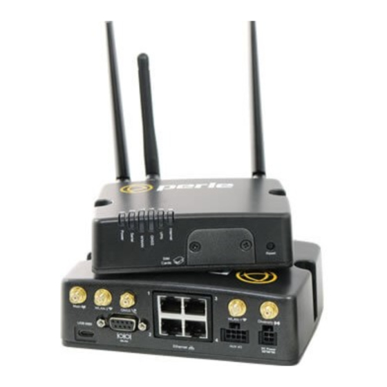
Perle IRG 5540 Hardware Installation Manual
Hide thumbs
Also See for IRG 5540:
- Hardware installation manual (49 pages) ,
- Quick start manual (4 pages) ,
- Installation manual (46 pages)

Subscribe to Our Youtube Channel
Related Manuals for Perle IRG 5540


Summary of Contents for Perle IRG 5540
- Page 1 Perle IRG 5540/5540+/5541/5541+ Hardware Installation Guide Updated: June 2023 Version A.06.13.2023 Document Part#:5500450-10 www.perle.com...
-
Page 2: Preface
This document does not cover how to configure your Perle IRG554x router. Information to configure your Perle router can be found in the Perle IRG7000/5000 5G/LTE Router User’s Guide and the Perle IRG7000/5000 5G/LTE Router Command Line Reference Guide on the Perle website. - Page 3 Perle IRG7000/5000 5G/LTE Router Command Line Interface Reference Guide using CLI Command Line Reference Guide commands to configure the IRG554x (this is an advanced way to configure the router). Perle IRG5540/5540+/5541/5541+ Router Hardware Installation Guide...
- Page 4 Perle IRG554x series router even if Perle has been advised or the possibility of such damages or they are foreseeable or for claims by any third party.
- Page 5 Cet équipement doit être utilisé dans les matières spécifiées par le fabricant. Warning: In case of malfunction or damage, no attempts at repair should be made by the user. Do not dismantle this product. In case of malfunction or damage, contact Perle Technical support at https://www.perle.com/support_services/support_request.aspx or email at https://www.perle.com/support_services/support_request.aspx#form...
- Page 6 Cet équipement est adapté à une utilisation dans les zones non dangereuses de classe I, division 2, groupes A, B, C, D Warning: WARNING-EXPLOSION HAZARD - Do not connect or disconnect equipment unless power has been removed or the area is known to be non-hazardous. Perle IRG5540/5540+/5541/5541+ Router Hardware Installation Guide...
- Page 7 être altérée. Warning: In case of malfunction or damage, no attempts at repair should be made. Do not dismantle the product. All repairs need to be made by a qualified Perle representative. Contact Perle Systems Technical support at https://www.perle.com/support_services/support_request.aspx or email at https://www.perle.com/support_services/support_request.aspx#form...
- Page 8 Series of Routers are trademarks of Perle. Copyright ©2023 Perle. 60 Renfrew Drive, Markham, Ontario, L3R 0E1, Canada All rights reserved. No part of this document may be reproduced or used in any form without written permission from Perle. Perle IRG5540/5540+/5541/5541+ Router Hardware Installation Guide...
- Page 9 Added IRG7440 model (5G) and updates to other models March 2022 A.03.17.2022 Updated Hot warning April 2022 A.04.08.2022 Updated Restricted Access Area warning June 2023 A.06.13.2023 Added DHCP/BOOTP (ZTP mode) support for factory default mode Perle IRG5540/5540+/5541/5541+ Router Hardware Installation Guide VIII...
-
Page 10: Table Of Contents
Table Of Contents Preface ............. . . I Overview . - Page 11 Relay Alarm ............23 Appendix A—Technical Specifications .
-
Page 12: Overview
• GPIO Cable with 8 Pin plug (#2500476) • 12VDC/2A 4 Pin (NA-#08000150, EU #08000160, UK #08000170, #08000180) power supply • GNSS PASV RP-Antenna SMA/CA (#08000130) order-able from Perle What You Need to Supply Before you can begin, you need to have the following: •... -
Page 13: Hardware
Operation starting after a boot is complete Normal Green—flashing Unit is powered up operation but normally—unit has no no config config. Unit is in Safe mode or Factory default mode. Fatal error Red—solid Red—solid Perle IRG5540/5540+/5541/5541+ Router Hardware Installation Guide... - Page 14 Serial Function Normal Low Power Meaning Mode Disabled or not Always off in power in use saving mode. Serial port/s Green—flashing TX/RX WWAN Function Normal Low Power Meaning Mode Disabled Perle IRG5540/5540+/5541/5541+ Router Hardware Installation Guide...
- Page 15 Function Normal Low Power Meaning Mode No VPN No VPN configured or enabled Green—solid VPN established—at established least 1 VPN connection is up. VPN failed Red—solid Red—blip Internet is up, but VPN failed Perle IRG5540/5540+/5541/5541+ Router Hardware Installation Guide...
- Page 16 Meaning Internet Mode Disconnected No connection by intention disabled or radio disconnect requested LTE primary if no Connected Green—solid Primary connection if WAN Backup mode Amber—solid Backup connection if WAN. Perle IRG5540/5540+/5541/5541+ Router Hardware Installation Guide...
-
Page 17: Sim Card/S
SIM Card/s The IRG554x supports two SIM cards. See Inserting the SIM card for the installation procedure. SIM/ Interface 1.8V/3V Back View ( IRG5541/5541+) Note: IRG5540 models do not have the WLAN-1 and WLAN-2 antennas. Perle IRG5540/5540+/5541/5541+ Router Hardware Installation Guide... -
Page 18: Antenna/S
Both LEDs Link + Flashing with activity 100 Mbps Right LED Green Link + Flashing with activity 10 Mbps No LAN connected GNSS Connector GPS+GLONAS+GAILEO Passive Antenna—SMA(M) straight connector for electrical details. Appendix A—Technical Specifications Perle IRG5540/5540+/5541/5541+ Router Hardware Installation Guide... -
Page 19: Connecting The Power
Alternatively it can be used simply as an analog input. GPIO Green User configurable digital input/output or GPIO analog voltage sensing input. Connect to switch, relay or external device. Note: Use copper conductors only. Perle IRG5540/5540+/5541/5541+ Router Hardware Installation Guide... -
Page 20: Aux/Io
The Router has one Normally Open (NO) relay (Pin 5 and Pin 1). The relay switch can be connected to an external powered device such as a siren or light to provide visual or audible notification of an alarm status. Ensure the power source is off prior to connection. Perle IRG5540/5540+/5541/5541+ Router Hardware Installation Guide... -
Page 21: Installation
1. Connect your cellular antenna to the SMA cellular antenna connector labeled Main. 2. Connect your GPS antenna to the SMA GPS antenna connector labeled GNSS. 3. Mount the GPS antenna where it has a good view of the sky (at least 90°). Perle IRG5540/5540+/5541/5541+ Router Hardware Installation Guide... -
Page 22: Connecting To The Ethernet Ports
It is used for: • Connect a serial device • Connect as a console port • As a GNSS output device Note: When connecting to a DCE device, a crossover cable is needed. Perle IRG5540/5540+/5541/5541+ Router Hardware Installation Guide... -
Page 23: Female Serial Pin Out
PC. 6. Press the Enter key on the keyboard and the prompt will display. See the Perle IRG7000/5000 5G/LTE Router CLI Reference Guide for more information on using CLI commands. Warning: If you connect or disconnect the console cable with the power applied to the router or any device on the network, an electrical arc can occur. -
Page 24: Connecting The Power
Molex part number 2451320420 or equivalent Rectangular socket to socket 6.56’ (2.00m) Before servicing this product ensure the power source has been disconnected. Electrical Note: installations should be performed by personnel thoroughly trained in safe electrical wiring procedures. Perle IRG5540/5540+/5541/5541+ Router Hardware Installation Guide... -
Page 25: Operation
DHCP offer Safe Mode Press the Reset button All LEDs, except Saves the startup config while powering up Power blink Boots with no config file Amber Allows you to do setup mode Perle IRG5540/5540+/5541/5541+ Router Hardware Installation Guide... -
Page 26: Fast Setup
Fast Setup mode allows you to quickly configure basic operating parameters on your router. Your Perle router has been shipped to you in Factory Default mode. On power up, your router is in “Fast Setup” mode with the Power LED flashing green. Make a connection to your router via the con- sole port or a Web browser, then answer basic setup operating parameters such as your initial user ID and password. -
Page 27: Managing The Irg554X
Perle Managed Media Converters, Ethernet Copper Extenders, Industrial Switches, IOLAN SCR/SCG and the IRG Series of Perle Routers. Your internet browser can securely access PerleVIEW and manage 10’s, 100’s or 1000’s of Perle devices from a centralized server. -
Page 28: Irg554X Router Deployment Modes
• Pin 2 (Ground)—Use the Black wire in the DC cable to connect Pin 2 to Ground. • Pin 3 (IGN–Ignition)—It is recommended to use the IGN wire (Pin 3) to initiate Standby mode on the IRG554x. Perle IRG5540/5540+/5541/5541+ Router Hardware Installation Guide... -
Page 29: Fixed Installation With Analog Input
• Pin 4 (GPIO)— In this example, the GPIO (green) used as an analog input to enter and exit Standby Mode. For more information on configuring Standby Mode, Timed Standby Mode and Event Handing see the Perle IRG7000/5000 5G/LTE Router User’s Guide. Perle IRG5540/5540+/5541/5541+ Router Hardware Installation Guide... -
Page 30: I/O Configurations
The voltage on Pin 4 when the high side pull-up is enabled (depends on the Vin and power consumption. Minimum Typical Maximum Units Source Current = 12 V = 36 V = 7 V Perle IRG5540/5540+/5541/5541+ Router Hardware Installation Guide... -
Page 31: Digital Output / Low Side Current Sink
Digital Output / Low Side Current Sink Use Pin 4 - GPIO as a low side current sink. State Minimum Typical Maximum Comments 200mA 850mA I_Typical = 25°C I_Min = 70°C I_Max = -40°C ––– ––– Perle IRG5540/5540+/5541/5541+ Router Hardware Installation Guide... -
Page 32: Digital Output / Open Drain
Digital Output / Open Drain You can use Pin 4—GPIO as an open drain to drive an external digital device. Pull-up State Minimum Typical Maximum Units Open Circuit ––– ––– ––– Active Low ––– ––– Perle IRG5540/5540+/5541/5541+ Router Hardware Installation Guide... -
Page 33: Aux /I/O
Digital input can also be used with the Standby Timer. Pull-up State Minimum Typical Maximum Units ––– ––– High ––– Perle IRG5540/5540+/5541/5541+ Router Hardware Installation Guide... -
Page 34: High Side Pull-Up / Dry Contact Switch Input
*Depending on the load, this value can range from Vin to Vin -2.5 Minimum Typical Maximum Units Source Current = 12 V = 36 V = 7 V -2.5 ––– Relay Alarm Normally Open (NO) dry contact 1A@24VDC Perle IRG5540/5540+/5541/5541+ Router Hardware Installation Guide... -
Page 35: Appendix A-Technical Specifications
2300(B30), 2300(B30), Bands 1500(B32), 1500(B32), TDD B41, 2100(B1), TDD B41. TDD TDDB42, 1900(B2), B42, TDD B43, TDDB43, TDD 1800(B3), TDD B46, CBRS B46, CBRS AWS(B4), B48, 1700(B66) B48, 1700)B66) 850(B5), 800(B8) Public Safety Bands Perle IRG5540/5540+/5541/5541+ Router Hardware Installation Guide... - Page 36 Dimensions: 41.9 x 47.3 x 16.3 mm / 1.65 x 1.86 x 0.64 in RG-174 Cable length: 5m / 16ft Wi-Fi IRG5000 IRG5500+ IRG5500+ FN Models with Intergrated IRG5521 IRG5521 IRG5521+ Wi-Fi IRG5541+ IRG5541+ FN IRG5541 LAN standards IEEE 802.11ac complaint & backward compatible with 802.11a/b/g/n Perle IRG5540/5540+/5541/5541+ Router Hardware Installation Guide...
- Page 37 IEEE 802.3ab for 1000Base-T IEEE 802.3x for Flow Control 1 x USB, Type-C Can be used as a console or additional Ethernet port. RS232 Serial DB9 Female connector Speeds 300bps-230Kbps or custom 15Kv ESD protection RS485 half-duplex Perle IRG5540/5540+/5541/5541+ Router Hardware Installation Guide...
- Page 38 (EN61000-4-5 differential and common modes) Vehicle Transient voltage Built-in protection against voltage transient including 5 protection VDC engine cranking and +200 VDC load dump Power Line Protection Surge: 8V (EN61000-4-5 common mode), 2KV (EN61000-4-5 differential and common modes Perle IRG5540/5540+/5541/5541+ Router Hardware Installation Guide...
- Page 39 Vibration: test method 514.6) SAE J1455 (Vibration: Section 4.10.4.1 and 4.10.4.2 Cab Mount, Shock: Section 4.11.3.4 Operational Shock) Hazloc IECEx/IECx, ATEX Class 1 Zone 2, Directive 2014/34/EU ANSI/ISA 12.12.01, Class 1 Division 2 Groups A-D, ISA 12.12.01-2015 Perle IRG5540/5540+/5541/5541+ Router Hardware Installation Guide...
- Page 40 9 kHz to 40 GHz) EN61000-3-2: 2014 (Limits for Harmonic Current Emissions) EN61000-3-3: 2013 (Limits of Voltage Fluctuations and Flicker) EN 61000-6-4:2007 + A1:2011 CISPR 32:2015/EN 55032:2015 Class A (Electromagnetic compatibility of multimedia equipment - Emission requirements) Perle IRG5540/5540+/5541/5541+ Router Hardware Installation Guide...
- Page 41 EN 301 908-13 v11.1.2:2017-07, ETSI EN 301 908-13 V11.1.2 (2017-07) (RF Conducted) EN 62311:2019, IEC 62311 Ed. 1.0 b:2007 (Human exposure restrictions for radio frequency electromagnetic fields) Cellular/Telecom IRG5540/5541+FCC/ICES, RED, PTCRB/CTIA, CE Regulatory Approvals IRG5541+ FN FCC/ICES, PTCRB/CTIA Environment Testing Perle IRG5540/5540+/5541/5541+ Router Hardware Installation Guide...
- Page 42 2.0 Typical Gain RHCP Polarization 4 dBic (typical) Axial Ratio at elevation 5 dB (typical) Vehicle Usage E-Mark (UN ECE Regulation 10.04, ISO 7637-2:2011 and ISOk 16750-2:2012) Vehicle Velocity 224 mph for cellular connectivity Perle IRG5540/5540+/5541/5541+ Router Hardware Installation Guide...
-
Page 43: Appendix B-Sample Labels
Appendix B—Sample Labels Perle IRG5540/5540+/5541/5541+ Router Hardware Installation Guide... -
Page 44: Appendix C-Mounting The Irg554X
2. Slide the two screws into the holding plate, then attach that holding plate to the router.Slide the two screws into the holding plate, then attach that holding plate to the router. Perle IRG5540/5540+/5541/5541+ Router Hardware Installation Guide... - Page 45 3. Position the router such that the top hooks of the DIN Rail clip attach onto the top of the DIN Rail. 4. Rotate the bottom of the router towards the rail. This will snap the bottom hooks of the DIN Rail clip into the bottom of the DIN Rail. Perle IRG5540/5540+/5541/5541+ Router Hardware Installation Guide...
-
Page 46: Appendix D-Mechanical
Appendix D—Mechanical Perle IRG5540/5540+/5541/5541+ Router Hardware Installation Guide... -
Page 47: Appendix E-Maintaining And Troubleshooting
• Ensure cables are not bent, constricted, close to high amperages, or exposed to extreme temperatures • Check that the Front panel LEDs are easily visible • Wipe case clean with a dry cloth—do not use solvents or cleaning agents Perle IRG5540/5540+/5541/5541+ Router Hardware Installation Guide...
Need help?
Do you have a question about the IRG 5540 and is the answer not in the manual?
Questions and answers