Tektronix TDS 220 Brief Introduction
Hide thumbs
Also See for TDS 220:
- Programmer's manual (250 pages) ,
- Service manual (120 pages) ,
- Programmer's manual (346 pages)
Advertisement
ECE 488: RF Circuits and Systems
Spring 2005
The Tektronix TDS 220 Oscilloscope
A Very Brief Introduction
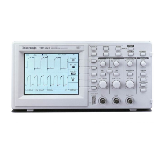
A Tektronix TDS 220 two-channel digital oscilloscope ("scope" or "Oscope" for short) is
pictured below with its controls grouped for easy recognition in the discussion that
follows.
Figure 1: Front panel of a Tektronix TDS 220 oscilloscope.
1.
Oscilloscope display
The LCD display replaces the cathode-ray tube used in older oscilloscopes. It adds
digital readouts of various settings and menu options. The example shown here displays
only Channel-1 on a voltage scale of 2 Volts per division (as indicated by
in
CH1 2.00V
the bottom-left corner of the display). The digit "1" with the arrow along the left edge
indicates the zero base line for the voltage of Channel 1. The time scale is set at
250 ns
-7
(250 nano-seconds or 2.5
10
seconds) per division. Since there are 10 divisions from
X
left to right, the display shows a total time of 2.5 µs (2.5 micro-seconds). The downward
pointing arrow at the middle of the screen's top edge indicates when triggering of the
display occurred (on a rising edge of the square wave). The leftward-pointing arrow
along the right side of the display indicates the voltage threshold that will trigger a sweep
of the trace. The items down the right side of the display indicate the functions of the
side-screen menu buttons for the particular menu (
) currently selected.
This
CH1
CORNELL UNIVERSITY
© WES SWARTZ (03/8/2)
1
Advertisement
Table of Contents

Related Manuals for Tektronix TDS 220


Summary of Contents for Tektronix TDS 220
- Page 1 Spring 2005 The Tektronix TDS 220 Oscilloscope A Very Brief Introduction A Tektronix TDS 220 two-channel digital oscilloscope (“scope” or “Oscope” for short) is pictured below with its controls grouped for easy recognition in the discussion that follows. Figure 1: Front panel of a Tektronix TDS 220 oscilloscope.
- Page 2 Figure 2. Here the same pulse-train signal is fed into both channels. Note Figure 2: Example of a two-trace display on the TDS 220. the change in the time base. 2. Vertical controls The vertical position and scaling of the traces for the two channels is controlled by the two sets of knobs shown in Figure 3.
- Page 3 Improper setting of the trigger TRIGGER VIEW controls can result in an overlay of confusing multiple traces, or no trace at all. A wonderful feature of the TDS 220 is the automatic setup feature initiated by the button (see Figure 1).
- Page 4 Don’t select a source that is not connected! 5. Handy buttons The cluster of three buttons in the top-right corner of the TDS 220 will prove to be quite useful. The button has already been mentioned under Trigger Controls, but it AUTOSET does much more.
- Page 5 6. Manual measurements using digital readouts The TDS 220 can display lines (called cursors) that can be manually placed to measure voltages and times. Suppose you want to measure the peak-to-peak voltage of a sinusoid that has some superimposed noise spikes. You can get a measure of this by setting the cursors (via the upper knobs in the Vertical Controls section) at positions that ignore the noise.
- Page 6 Figure 8: Time measurements using the which is the length of the period, cursors. and the frequency (reciprocal of the period). Acknowledgements: My thanks to some unknown author for producing the pictures of the TDS 220 used here. CORNELL UNIVERSITY © WES SWARTZ (03/8/2)
Need help?
Do you have a question about the TDS 220 and is the answer not in the manual?
Questions and answers