
Related Manuals for Shure A400MB


Summary of Contents for Shure A400MB
- Page 1 A400MB Mute Button Shure A400MB online user guide. Includes installation instructions, DIP switch settings, specifications, and more. Version: 1.0 (2021-G)
-
Page 2: Table Of Contents
Shure Incorporated Table of Contents A400MB Pin Assignments A400MB Mute Button DIP Switches IMPORTANT SAFETY INSTRUCTIONS Accessing the DIP Switches DIP Switch Settings Mute Button Overview Connections and Signal Flow A400MB Parts What's in the Box Optional Accessories Installing the Mute Button... -
Page 3: A400Mb Mute Button
Shure Incorporated A400MB Mute Button IMPORTANT SAFETY INSTRUCTIONS READ these instructions. KEEP these instructions. HEED all warnings. FOLLOW all instructions. DO NOT use this apparatus near water. CLEAN ONLY with dry cloth. DO NOT block any ventilation openings. Allow sufficient distances for adequate ventilation and install in accordance with the manufacturer’s instructions. -
Page 4: Mute Button Overview
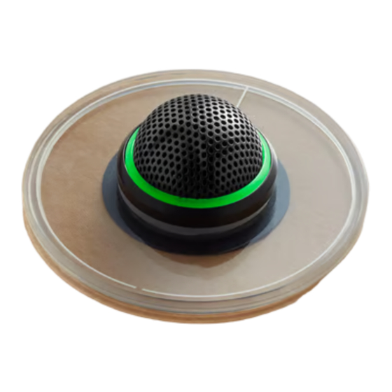
Mute Button Overview The Shure A400MB mute button accessory is compatible with the MX395-LED and MX400SMP, with a low profile design ideal for surface mounting to boardroom tables. The switch adds a programmable button for microphone LEDs and local or remote mute control with Shure products or third-party control systems. -
Page 5: A400Mb Parts
Shure Incorporated A400MB Parts ① Color Ring Place around drilled hole to match microphone color. ② Mute button Touch to mute microphone. ③ Mute button cable Connect to the plug-on adapter. ④ Spacer Use the spacer to adjust to different table thicknesses. Pull the mute button cable through the gap. -
Page 6: Installing The Mute Button
Shure Incorporated • Assembly kit (90A48840): ◦ Flathead screwdriver ◦ Cable ties (2) ◦ Strain reliefs (2) ◦ Terminal plug Installing the Mute Button The mute button fits in tables that are between 15 to 30 mm (.59 to 1.18 inches) thick. - Page 7 Shure Incorporated 7/16...
-
Page 8: Phantom Power
Use the included 6-pin block connector to wire the microphone to a DSP or other logic-enabled device, such as the ANI22- BLOCK or ANI4IN-BLOCK. A400MB Pin Assignments 6-pin block connector Note: The block connector screw terminals face downwards so they are accessible from under the table after installation. -
Page 9: Dip Switches
Shure Incorporated 6. Audio + DIP Switches Accessing the DIP Switches Disconnect the adapter from the A400MB and any logic devices before disassembly. Remove the 2 Phillips head P1 size screws from the base of the adapter. 9/16... - Page 10 Shure Incorporated 10/16...
-
Page 11: Dip Switch Settings
Connect the A400MB switch (output) to the ANI switch (input) to send a logic signal from the A400MB to the ANI.* Set DIP switch 3 to up. This disables local muting. Pressing the A400MB sends a logic signal (the microphone passes audio regardless of whether the button is pressed or not). - Page 12 Shure Incorporated 5. Set DIP switch 4 to configure microphone LED color. *Note: The A400MB connector plugs in upside down relative to the ANI connector. The cable should be wired in a 1:1 pinout configuration when both connec tors face the same direction. 12/16...
-
Page 13: Connections And Signal Flow
Shure Incorporated Connections and Signal Flow ① MX395-LED: Runs the audio signals and features logic connections to receive logic mute and LED control signals. ② A400MB: 13/16... -
Page 14: Optional Accessories
Provides IntelliMix processing for videoconferencing software. ⑥ Computer: Connects to P300 USB to provide mute synchronization with videoconferencing software, such as Microsoft Teams or Zoom. Visit www.shure.com for more information on how to configure the ANI22IN-BLOCK and P300. Optional Accessories Remote Mounting Kit... -
Page 15: Important Product Information
1.93 x 1.93 x 0.05 in. (49 x 49 x 1.2 mm) H x W x D Important Product Information The equipment is intended to be used in professional audio applications. Changes or modifications not expressly approved by Shure Incorporated could void your authority to operate this equipment. Note: Testing is based on the use of supplied and recommended cable types. The use of other than shielded (screened) cable types may degrade EMC per formance. Please follow your regional recycling scheme for batteries, packaging, and electronic waste. - Page 16 This product meets the Essential Requirements of all relevant European directives and is eligible for CE marking. The CE Declaration of Conformity can be obtained from Shure Incorporated or any of its European representatives. For contact information please visit www.shure.com...
Need help?
Do you have a question about the A400MB and is the answer not in the manual?
Questions and answers