
Related Manuals for Motorola MTM5 00 Series


Summary of Contents for Motorola MTM5 00 Series
- Page 1 MTM5x00 / MTM800 FuG MTM800 FuG ET BASIC SERVICE MANUAL 380–430 MHz (MT953C/MT953CG) *68015000183* November 2012 68015000183-D © 2012 Motorola Solutions, Inc. All rights reserved.
- Page 3 Service Manuals need to be updated accordingly. If you wish to be informed of these updates, kindly fill in and fax us your details. Fax to: 6-04-6124944 The Technical Publications Coordinator, Global Customer Documentation, R&D Department, Motorola Penang. Your Details Name/Contact Person: Company Name: Address: Telephone No.: Fax No.:...
-
Page 4: Service Manual Feedback Form
Kindly take a few moments to provide feedback on this manual. Thank you for your cooperation. Fax to: 6-04-6124944 The Technical Publications Coordinator, Global Customer Documentation, R&D Department, Motorola Penang. 1. Please check all the appropriate boxes: Disassembly Procedures Alignment Procedures... -
Page 5: Copyright
Accordingly, any copyrighted Motorola computer programs contained in the Motorola products described in this manual may not be copied, reproduced, modified, reverse-engineered, or distributed in any manner without the express written permission of Motorola. - Page 6 COPYRIGHT Notes...
-
Page 7: Document History
DOCUMENT HISTORY DOCUMENT HISTORY The following major changes have been implemented in this manual since the previous edition: Edition Description Date 68015000183-A Initial Release Nov. 2010 68015000183-B Updates include: May. 2011 • added new microphone to the Accessories-to- Model Chart on page 2-4. •... - Page 8 viii DOCUMENT HISTORY Notes...
-
Page 9: Vehicles Or As Fixed Site Control Stations
These recommended RF exposure levels include substantial margins of protection. All Motorola 2-way terminals are designed, manufactured and tested to ensure they meet government-established RF exposure levels. In addition, manufacturers also recommend specific operating instructions to users of 2-way terminals. -
Page 10: Federal Communications Commission Regulations (Us Markets Only)
RF exposure and to satisfy compliance requirements. Compliance with RF Exposure Standard Your Motorola terminal is designed and tested to comply with a number of national and international standards and guidelines (listed below) regarding human exposure to radio frequency electromagnetic energy. -
Page 11: Rf Exposure Compliance And Control Guidelines And Operating Instructions
40 to 110 Watts 90 cm (3 Ft) Note: If you are not sure of the rated power of your terminal, contact your Motorola representative or dealer and supply the terminal model number found on the terminal model label. If you cannot determine the rated power out, then assure 90cms (3 feet) separation from the body of the vehicle. -
Page 12: Approved Accessories
RF Safety Standards. Approved Accessories • This terminal has been tested and meets the RF Safety Standards when used with the Motorola accessories supplied or designated for this product. Use of other accessories may result in non- compliance with RF Safety Standards. -
Page 13: Facilities
Product Safety and RF Exposure xiii Facilities To avoid electromagnetic interference and/or compatibility conflicts, turn off your terminal in any facility where posted notices instruct you to do so. Hospitals or health care facilities may be using equipment that is sensitive to external RF energy. Vehicles To avoid possible interaction between the terminal transmitter and any vehicle electronic control modules, such as, ABS, engine, or transmission controls, the terminal should be installed only by an... -
Page 14: Operational Warnings
Product Safety and RF Exposure OPERATIONAL WARNINGS W A R N I N G For Vehicles With Air Bags Do not mount or place a mobile terminal in the area over an air bag or in the air bag deployment area. -
Page 15: Additional Important Information
Dieses Gerät ist mit einer Schutzsicherung im Stromversorgungskabel ausgestattet. Bei Austausch ausschließlich den Originalwert verwenden WARNUNG: Bei Einsetzen von nicht vom Hersteller freigegebenen Ersatzteilen kann das Gerät zerstört werden. Sicherung für Stromversorgungskabel GKN6270/GKN6274: 10A (Motorola Best.-Nr.:65C80283E05) Sicherung für Zündungserkennungskabel HKN9327: 4A (Motorola Best.-Nr.:65C80283E02) Sicherung für Y Kabel PMKN4133/PMKN4134:... - Page 16 Product Safety and RF Exposure Notes...
-
Page 17: Table Of Contents
CONTENTS xvii CONTENTS Technical Information Updates ......... . . Service Manual Feedback Form . -
Page 18: Contents
xviii CONTENTS CHAPTER 3 OVERVIEW General ............Digital Modulation Technique . - Page 19 CONTENTS Disassembling and Reassembling the Terminal – General....Terminal Disassembly and Reassembly – Detailed ..... . . Enhanced Control Head Removal .
- Page 20 CONTENTS APPENDIX B PRODUCT SPECIFIC INFORMATION Equipment Electrical Ratings......... . . Normal Load Conditions: .
-
Page 21: Scope Of This Manual
Scope & Warranty Information 1 - 1 CHAPTER 1 SCOPE & WARRANTY INFORMATION Scope of this Manual This manual is intended for use by trained service technicians familiar with similar types of equipment only. It contains information required for the installation of the equipment described and is current as of the printing date. -
Page 22: Manuals & User Guides
68015000183 MTM5400 / MTM800 FuG Basic Service Manual (English) User Guides 68015000289 MTM5x00 Quick Start Guide (English) 68015000180 MTM5x00 Feature User Guide (English) only available on MOL: (http://www.motorola.com/emeaonline) 68015000284 MTM5x00 Quick Start Guide (Lithuanian) 68015000285 MTM5x00 Quick Start Guide (Arabic) 68015000290 MTM5x00 Quick Start Guide (Spanish) - Page 23 68015000585 MTM800 FuG / MTM800 FuG ET Feature User Guide (English) 68015000552 MTM800 FuG / MTM800 FuG ET Feature User Guide (English, German) All the Feature User Guides above are only available on MOL: (http://www.motorola.com/emeaonline) CPS Start Up Manual 6802974C10...
-
Page 24: Warranty And Service Support
“return for repair” warranty, a check of the product should be performed prior to shipping the unit back to Motorola. This is to ensure that the product has been correctly programmed or has not been subjected to damage outside the terms of the warranty. -
Page 25: Chapter 2 Model Information & Accessories
Model Information & Accessories 2 - 1 CHAPTER 2 MODEL INFORMATION & ACCESSORIES MTM5x00/MTM800 FuG/MTM800 FuG ET with Enhanced Control Head Mobile Terminal Model Information This manual applies to the following Mobile Terminal Models: Type No. Sales Model No. Short Description Model MT953C M83PFS6TZ5AN... -
Page 26: Model Specifications
2 - 2 Model Information & Accessories Model Specifications GENERAL RECEIVER TRANSMITTER π ETSi: ETS 300 394-1 Receiver Type: Direct Modulation Type: /4DQPSK Conversion 4-QAM 16-QAM 64-QAM Type Number: Frequency Range: RF Power: MTM5400/MTM800 FuG MT912M MTM5400 / 380–430 MHz 10 W / 40 dBm ENH 380–430 MHz MTM800 FuG... -
Page 27: Model Descriptions
Model Information & Accessories 2 - 3 Model Descriptions Model Description Dash Mount with Mobile Terminal with Direct Mount Enhanced Control Head, Speaker, Microphone or Handset, Standard User Guide, and Installation Accessories. Desk Mount with Mobile Terminal with Direct Mount Enhanced Control Head, Speaker, Microphone or Handset, Standard User Guide, Installation Accessories and Tray with power supply. - Page 28 2 - 4 Model Information & Accessories ACCESSORIES Motorcycle Mount Enhanced Control Head, PMWN4008 Hungarian Keypad Expansion & Remote Head Kits Part Number Data Expansion Head PMLN4908 Remote Head PMLN4904 Ethernet Data Expansion Control Head PMLN7009 Remote Ethernet Control Head PMWN4024 Telephone Style Control Head PMWN4025...
- Page 29 Model Information & Accessories 2 - 5 ACCESSORIES Gooseneck PTT RLN4858 Pushbutton with Remote PTT RLN4857 Push Button PTT RLN5926 Desktop & Data Box Mount Part Number Desktop Tray without Loudspeaker GLN7318 Desktop Tray with Loudspeaker RSN4005A Desktop Power Supply HPN4007C Desktop Power Supply GPN6145B...
- Page 30 2 - 6 Model Information & Accessories ACCESSORIES 12V Power Cable to Battery, 3m with Fuse (10 A) GKN6270 12V Power Cable to Battery, 6m with Fuse (10 A) GKN6274 Ignition Sense Cable PMKN4120A Installation Part Number External Alarm Relay GKN6272 Accessory Connector Kit - radio rear 26-pin plug HLN9457...
- Page 31 Model Information & Accessories 2 - 7 ACCESSORIES Antenna Mount Panel/Roof thickness up to 4mm GMLN4276A Antenna Mount Panel/Roof thickness up to 6mm GMLN4277A Antenna Mount Magnetic GMLN4278A Antenna Whip Tetra Flexible Hinged 380 – 400 MHz GMAE4279A Antenna Whip Tetra Flexible Hinged 410 – 430 MHz GMAE4280A Antenna Whip Tetra Flexible Hinged 380 –...
- Page 32 2 - 8 Model Information & Accessories Notes...
-
Page 33: Chapter 3 Overview
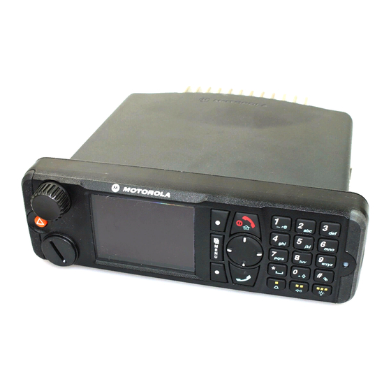
OVERVIEW General The MTM5400/MTM800 FuG with Enhanced Control Head is Motorola’s latest and most advanced digital mobile TETRA terminal. This terminal generation is based on a new digital platform technology which takes care of the linear modulation type of terminals to support the TETRA needs. -
Page 34: Voice Compression Technology
3 - 2 Overview Voice Compression Technology Voice is converted into a digital bit stream by sampling the voice at high rate and converting the samples into numbers, which are represented by bits. Voice compression reduces the number of bits per second while maintaining the voice at an acceptable quality level. -
Page 35: Chapter 4 Programming The Terminal
Programming the Terminal 4 - 1 CHAPTER 4 PROGRAMMING THE TERMINAL Note: For programming the terminal, refer to TETRA Customer Programming Software (CPS) Start-up User Guide, Publication No. 6802974C10_. - Page 36 4 - 2 Programming the Terminal Notes...
-
Page 37: Chapter 5 Test Setup & Testing
Any level 3 repairs can deeply affect the performance of the MTM5400 with Enhanced Control Head terminal and may cause a new tuning procedure. This tuning procedure can only be applied by certain authorized Motorola W A R N I N G depots where the appropriate TEST&TUNE EQUIPMENT is available. - Page 38 5 - 2 Test Setup & Testing Notes...
-
Page 39: Chapter 5.1 Test Setup & Testing For 380-430 Mhz
W A R N I N G This tuning procedure can only be applied by certain authorized Motorola depots where the appropriate TEST&TUNE EQUIPMENT is available. The appropriate TEST&TUNE EQUIPMENT is a special automated test equipment which is only available at some Motorola factories and Motorola repair centers. -
Page 40: Test Equipment
5.1 - 2 Test Setup & Testing for 380–430 MHz Test Equipment The table below lists the special test equipment required for servicing TETRA mobile terminals. Table 5.1-1 Test Equipment Name Part Number Digital Multimeter R1072_ 220V Power Supply R1011_/220V TETRA SVC MON. -
Page 41: Receiver Tests
Test Setup & Testing for 380–430 MHz 5.1 - 3 Table 5.1-2 Test Setup (Continued) Test Name Test Setup Terminal Setup Test Conditions Limits Transmitter Tests RF Gen Level Range 1 -90dBm Test Group 1 Burst Power 35 – 40dBm Timing Error <=0.25 Symbols Frequency... -
Page 42: Call Processing Tests
5.1 - 4 Test Setup & Testing for 380–430 MHz Call Processing Tests 1. Talk Back 2. Call to Mobile Duplex Test 1. Digital Duplex Test (Tx) Measurement Capabilities: Bar chart display for Tx Power, Frequency Error, Vector Error RMS, Power Analyzer, Spectrum Analyzer, Vector Analyzer, Vector Diagrams. - Page 43 Test Setup & Testing for 380–430 MHz 5.1 - 5 4. Configure the parameters for the “System ID and Access Parameters”. a. Press the “Config” soft key twice, then go to “Configure”, followed by “System ID & Access Parameters”, and press the “Select” soft key. b.
-
Page 44: Configuration Of The Ifr 2968 System Setup
5.1 - 6 Test Setup & Testing for 380–430 MHz b. Enter the parameters outlined below: Broadcast: Not supported Broadcast Interval: Neighbour Cell Channel: 3500 Neighbour Cell Location Area: Neighbour Cell Identifier: Slow Re-select Threshold Above Fast: 10dB Fast Re-select Threshold: 10dB Slow Re-select Hysteresis: 10dB... - Page 45 Test Setup & Testing for 380–430 MHz 5.1 - 7 7. Press the “More” soft key if the Type cannot be seen. Note: If the required Mobile soft key in step 6 and step 7 is not displayed, the system needs to be set up manually as in step 8. If the MS type was chosen in step 6 and step 7, continue with step 9.
- Page 46 5.1 - 8 Test Setup & Testing for 380–430 MHz 14. Press the “Location Area” soft key. Thereafter, enter “224” and press the “Location Area” soft key. 15. Press the “Min Rx Level” soft key. Thereafter, enter “-110dBm” and press the “Min Rx Level” soft key. 16.
-
Page 47: Configuration Of The Ifr 2968 Manual Test Screen
Test Setup & Testing for 380–430 MHz 5.1 - 9 29. Press the “Signal Type” soft key and “Direct set-up” soft key. 30. Press the “Priority” soft key. Thereafter, enter “00” and press the “Priority” soft key. 31. Leave “Calling Party SSI” setting to default value. 32. -
Page 48: Rf Tests
5.1 - 10 Test Setup & Testing for 380–430 MHz RF Tests Receiver Tests Simulate Base Station (registration) 1. Turn the terminal ON. When the terminal is in Trunked Mode, continue with step 2. Otherwise perform steps a through c. a. -
Page 49: Transmitter Tests
Test Setup & Testing for 380–430 MHz 5.1 - 11 10. Press “Trace” using the Lower (soft) key. Note: RSSI results will flash on the screen every few seconds. The display shows: SERV: 0/34348 RSSI: -90 CX: 20 CHQ: 99/E0 Disregard the “SERV”, “CX”... -
Page 50: Call Processing Test
5.1 - 12 Test Setup & Testing for 380–430 MHz 6. Press the “PTT” of the terminal and monitor the IFR “Manual Test” screen which dis- plays the Power Profile, Burst Power, Timing Error, Frequency Error and Vector Error. Note: You have to hold the PTT in the pressed position long enough to enable you to read the results. -
Page 51: Duplex Test (Phone/Private Mode)
Test Setup & Testing for 380–430 MHz 5.1 - 13 Duplex Test (Phone/Private Mode) Digital Duplex Test (Tx) 1. In the IFR Manual Test Mode press the “RF Gen Level” soft key. Enter “-50dBm” by pressing the data keys and “RF Gen Level” key. 2. -
Page 52: Manual Mode Testing
5.1 - 14 Test Setup & Testing for 380–430 MHz 11. Monitor the diagram for the following: • press “vector error” soft key for vector error. • press “mag error” soft key for magnitude error. • press “phase error” soft key for phase error. •... - Page 53 Test Setup & Testing for 380–430 MHz 5.1 - 15 6. Press any key consecutively. The display shows the backlight brightness levels “min”, “low”, “med” and “max”. Verify the brightness of the display. Note: At level “min” the display contents is not visible. 7.
-
Page 54: Service Flow Chart (Board Level)
If fuse F602 or F603 needs to be replaced use Motorola part no. Switch on the radio and observe the display 6586808Y13 at power up. The radio must be completely (see figure on following pages). -
Page 55: Fuses On The Mainboard
TP629 R685 TP_VAUDIO_ C662 L603 R1754 R684 C6115 2.7V TP602 C1717 C6134 U100 Q1702 E616 C1729 C660 SH601 Fuses (Motorola Part Number: R1733 L605 R1709 C1705 C1704 C1709 R1710 R1797 SH603 U1701 U1702 E1701 R980 R6192 R1798 R981 C1701 R1707... - Page 56 5.1 - 18 Test Setup & Testing for 380–430 MHz Notes...
-
Page 57: Chapter 6 Maintenance
Maintenance 6 - 1 CHAPTER 6 MAINTENANCE Introduction This chapter provides details about the following: • Preventive maintenance (inspection and cleaning) • Safe handling of CMOS and LDMOS devices • Pre-baking of Integrated Circuits • Repair procedures and techniques • Disassembly and reassembly of the terminal •... -
Page 58: Cleaning External Plastic Surfaces
6 - 2 Maintenance CAUTION: Use all chemicals as prescribed by the manufacturer. Be sure to follow all safety precautions as defined on the label or material safety data sheet. CAUTION: The effects of certain chemicals and their vapors can have harmful results on certain plastics. -
Page 59: Safe Handling Of Cmos And Ldmos Devices
• Ground the working surface of the service bench to protect the CMOS/LDMOS device. We recommend using the Motorola Static Protection Assembly (part number 0180386A82), which includes a wrist strap, two ground cords, a table mat, a floor mat, ESD shoes, and an ESD chair. -
Page 60: General Repair Procedures And Techniques
When damaged parts are replaced, identical parts should be used. If the identical replacement component is not locally available, check the parts list for the proper Motorola part number and order the component from the nearest Motorola Communications parts center listed in the “Piece Parts”... -
Page 61: Pre-Baking Of Integrated Circuits
Maintenance 6 - 5 For soldering components with Hot-Air or infra red solder systems, please check your user guide of the solder system to get information on solder temperature and time for the different housings of the integrated circuits and other components. Pre-baking of Integrated Circuits Electronic components are generally coated with plastic material which has the nature of not being waterproof. -
Page 62: Repair Procedures And Techniques - General
When damaged parts are replaced, identical parts should be used. If the identical replacement part is not locally available, check the parts list for the proper Motorola part number and order the part from the nearest Motorola Communications parts center listed in the “SUPPORT CENTRES”... -
Page 63: Terminal Disassembly And Reassembly - Detailed
Enhanced Control Heads, Remote Head Enhanced and Data Expansion Head Enhanced on terminal models. Enhanced Control Head Removal Insert the dismantling tool (Motorola part number 6686119B01) in the chamfer between the Enhanced Control Head and the terminal assembly. Figure 6-1 Typical Enhanced Control Head Removal Push down the handle of the dismantling tool to pry open the control head until the chassis tabs disengage from the Enhanced Control Head at both sides. -
Page 64: Top Plastic Cover Removal
6 - 8 Maintenance Top Plastic Cover Removal Insert the dismantling tool in the middle of the terminal assembly side groove. Dismantling Tool ZWG0130211-O Figure 6-3 Top Cover Removal Pull and maneuver the sides of the top plastic cover, until the cover is released from the terminal chassis. - Page 65 The diecast cover may be difficult to remove due to the main seal adhesion, if the diecast cover has not been removed for a long time. The dismantling tool (Motorola part number 6686119B01) can be used as a lever to pry and remove the diecast cover.
-
Page 66: Sim Dust Cover Removal
6 - 10 Maintenance Remove the two PCB screws using a T20 TORX driver. PCB screws Figure 6-7 Connector Clips, Accessory Connector and PCB Screws Removal Lift the front edge of the transceiver board (the edge that mates with the Enhanced Control Head), and pull it towards the front of the terminal. - Page 67 Maintenance 6 - 11 Clean thermal pad contact surfaces on the diecast with isopropyl alcohol (100%) applied on a soft, absorbent, lintless cloth or tissue before new thermal pads are applied. Place the new thermal pads at the bottom of the diecast using a blunt-tipped tweezer. Align the pre-driver heat sink thermal pad’s corner with the alignment feature on the bottom diecast.
- Page 68 6 - 12 Maintenance Tighten the two PCB screws with 1.9 Nm (17 lbin) using a T20 TORX driver following the sequence specified on the PCB. 10. Connect the GPS MCX connector to the board’s GPS connector. 11. Connect the plastic accessory connector housing. Figure 6-11 Assembling the GPS Cable Bulkhead 12.
-
Page 69: Sim Dust Cover Assembly
Maintenance 6 - 13 SIM Dust Cover Assembly Place the SIM dust cover in place before placing the SIM dust cover plate. Tighten the screw with 0.23 Nm (2 lbin) using a Phillips screwdriver. Figure 6-13 SIM Dust Cover Assembly CAUTION: Ensure that the dust cover is flushed with the diecast surface. -
Page 70: Enhanced Control Head - Disassembly
6 - 14 Maintenance – Enhanced Control Head Disassembly Remove the middle screw from the back of the Enhanced Control Head using a T10 TORX™ as shown in the following figure. Figure 6-14 Middle Screw Removal To dismount the Enhanced Control Head front housing from the back housing, insert the dismantling tool in the groove between the two housings as shown in the following figure. -
Page 71: Enhanced Control Head - Reassembly
Maintenance 6 - 15 ZWG0130215-O Figure 6-16 Enhanced Control Head Board Removal Remove the keypad by gently pressing the keypad out from the Enhanced Control Head front housing. NOTE: Care should be taken not to touch or contaminate the conductive pads on the under side of the keypad or the conductive contacts on the printed circuit board. -
Page 72: Remote Head Enhanced - Disassembly
To Disassemble the Remote Head Enhanced from the Terminal: Remove the Remote Enhanced (PMLN4904_) from the terminal by inserting the dismantling tool (Motorola part number 6686119B01) in the chamfer between the Remote Head Enhanced and the terminal assembly. Use the dismantling tool to push and pry until the chassis tabs disengage from the Remote Head Enhanced on both sides. -
Page 73: Remote Head Enhanced - Fitting
Maintenance 6 - 17 Remote Back Housing Remote Head Enhanced Remote Back Head 10-pin Connector Figure 6-18 Remote Mount Enhanced Control Head with Remote Head Enhanced – Remote Head Enhanced Fitting To Fit the Remote Front Housing: Connect the flex from the Remote Head Enhanced to the top small connector in the terminal with the 'dot' or 'O' facing upwards away from the terminal;... -
Page 74: Remote Mount Enhanced Control Head - Reassembly
6 - 18 Maintenance Remove the board from the Remote Mount Enhanced Control Head front housing by unscrewing the screws using T10 TORX and disassemble the encoder switch flex from the socket on the board. Remove the board from the Remote Mount Enhanced Control head front housing by stretching the Remote Mount Enhanced Control Head front housing and pulling up the board. -
Page 75: Data Expansion Head Enhanced - Disassembly
To Disassemble the Data Expansion Head Enhanced from the Terminal Remove the Data Expansion Head Enhanced (PMLN4908_) from the terminal by inserting the dismantling tool (Motorola part number 6686119B01) in chamfer between the Data Expansion Head Enhanced and the terminal assembly. -
Page 76: Data Expansion Head Enhanced - Reassembly And Fitting
6 - 20 Maintenance To Disassemble the Connector Board from Expansion Head Housing Remove the silicon rubber frame. Remove the four screws from the connector board. Remove all the protection caps on the front of the expansion head housing. Lift the connector board from the expansion head housing. –... -
Page 77: Motorcycle Mount Enhanced Control Head - Disassembly
Maintenance 6 - 21 – Motorcycle Mount Enhanced Control Head Disassembly To disassemble the Motorcycle Mount Enhanced Control Head: Unscrew the screws of the Motorcycle Mount Enhanced Control Head trunnion and remove the Motorcycle Mount Enhanced Control Head from the trunnion. Twist and pull out the telco cable from the connector. -
Page 78: Motorcycle Mount Enhanced Control Head - Reassembly
To Disassemble the Remote Ethernet Expansion Head from the Terminal: Remove the Remote Ethernet Expansion Head (PMLN7009_) from the terminal by inserting the dismantling tool (Motorola part number 6686119B01) in the chamfer between the Remote Ethernet Expansion Head and the terminal assembly. -
Page 79: Remote Ethernet Expansion Head - Fitting
Maintenance 6 - 23 – Remote Ethernet Expansion Head Fitting To Fit the Remote Ethernet Expansion Head to the Terminal: Connect the 40pos flex from the Remote Ethernet Expansion Head to the 40pos connector in the terminal on the left facing downwards to the terminal chassis; make sure the gold pads on the flex are facing upwards to the terminal top cover with the “1”... -
Page 80: Telephone Style Control Head - Disassembly
6 - 24 Maintenance – Telephone Style Control Head Disassembly Unlatch the Handset from the Cradle as shown in Figure 6-23. Handset Cradle ZWG0130214 O Figure 6-23 Handset Removal Remove the four screws from the back of the Cradle using a T10 TORX™ screw bit. Remove these four screws to disassemble the Cradle back housing... - Page 81 Maintenance 6 - 25 Spiral cord cable ZWG0130215-O Figure 6-25 Cradle Back Housing Assembly Removal Remove the main PCB from the Cradle front housing by unfastenning the two self tapping screws using a T10 TORX™ screw bit. Remove the spiral cord retainer from the Cradle front housing. Spiral cord retainer ZWG0130215-O Figure 6-26 Main PCB Removal...
- Page 82 6 - 26 Maintenance Remove the spiral cord cable from the Cradle front housing by pulling back the strain relief and carefully push the wire to board connector in vertical position out from the Cradle front housing as shown in Figure 6-28 below. Strain relief Wire to board Make sure the wire to board...
- Page 83 Maintenance 6 - 27 12. Remove the main PCB from the Handset back housing by unfastenning the four self tapping screws using a T7 TORX™ screw bit. 13. Unplug the earpiece and microphone wire to board connectors from the Handset main PCB. Remove the Handset main PCB from the Handset back housing.
- Page 84 6 - 28 Maintenance 18. Pull back the strain relief of the spiral cord cable by pushing the spiral cord inside towards the Handset front housing. Wire to board connectors Strain relief Pull out strain relief Front housing ZWG0130215-O Push in spiral cord Figure 6-34 Spiral Cord Cable Connectors Removal 19.
-
Page 85: Telephone Style Control Head - Reassembly
Maintenance 6 - 29 – Telephone Style Control Head Reassembly To assemble the Spiral Cord Cable assembly, slot in the two wire to board connectors into the Handset front housing. ZWG0130215-O Figure 6-37 Spiral Cord Cable Removal 2 Assemble the wire to board connectors to the keypad flex as shown in Figure 6-38. Connect both wire to board connectors to their respective sockets ZWG0130215-O... - Page 86 6 - 30 Maintenance ZWG0130215-O Ensure the keypad flex Push the spiral is align to the guiding pin cord cable away on the front housing from front housing Push the spiral cord strain relief inwards towards front housing Figure 6-39 Keypad Retainer Assembly Assemble the spiral cord cable retainer as shown below.
- Page 87 Maintenance 6 - 31 Assemble the micro-USB BTB connector to the keypad flex. Micro-USB module Figure 6-41 Micro-USB Module Assembly Assemble the earpiece and microphone wire to board connectors to the Handset main PCB. Assemble the Handset main PCB to the Handset front housing by aligning to the PCB to the front housing’s guiding pin as shown in Figure 6-42 below.
- Page 88 6 - 32 Maintenance Machined screws ZWG0130215-O Figure 6-44 Back Housing Assembly 13. Twist the spiral cord wire to board connector to vertical postion as shown below and insert through the Cradle front housing as illustrated in Figure 6-45. Twist the wire to board connector to vertical position before inserting through the front housing ZWG0130215-O...
- Page 89 Maintenance 6 - 33 15. Connect the spiral cord cable wire to board connector to the Cradle main PCB. Cradle main PCB Spiral cord cable wire to board connector ZWG0130215-O Figure 6-47 Spiral Cord Cable Connector Assembly 16. Assemble the Cradle main PCB to the Cradle front housing by aligning the PCB to the front housing guide pins.
- Page 90 6 - 34 Maintenance Main screws ZWG0130215-O Figure 6-49 Cradle Back Housing Assembly Installation 1 ZWG0130215-O Figure 6-50 Cradle Back Housing Assembly Installation 2 20. Latch the Handset back on the Cradle as shown in Figure 6-51 below. ZWG0130215-O Figure 6-51 Handset Assembly...
-
Page 91: Service Aids
The following table lists the service aids recommended for working on the terminal. While all of these items are available from Motorola, most are standard workshop equipment items, and any equivalent item capable of the same performance may be substituted for the item listed. -
Page 92: Exploded Views & Parts Lists
Exploded Views & Parts Lists NOTE: For optimum performance, all replacement parts, diodes, transistors and integrated circuits must be ordered by Motorola part numbers. Transceiver – Exploded View and Parts List Figure 6-52 Transceiver Exploded View Terminals with special label OPTION BOARD MOUNTED (see dotted lines on figure above) NOTE: are equipped with an additional board inside the transceiver cover plate. - Page 93 Maintenance 6 - 37 Table 6-5 Transceiver Parts List Item No. Description Part Number Chassis 27012003001 Gasket, Enhanced Control Head 3202620Y01 Screw, (M2X0.4) 0378341A01 SIM dust cover plate 64012011001 SIM dust cover 32012066001 Pre-driver heat sink thermal pad 75012083001 RF PA thermal pad 75012082001 GPS cable 3015953H01...
-
Page 94: Enhanced Control Head - Exploded View And Parts List
6 - 38 Maintenance Enhanced Control Head – Exploded View and Parts List ZWG0130201-O Figure 6-53 Enhanced Control Head – Exploded View 1 Table 6-6 Enhanced Control Head – Parts List 1 Item No Description Part No. GCAI Cover 1515048C01 Keypad Assembly –... - Page 95 Maintenance 6 - 39 11 11 ZWG0130201-O Figure 6-54 Enhanced Control Head – Exploded View 2 Table 6-7 Enhanced Control Head – Parts List 2 Item Item Description Part No. Description Part No. Main PWA Kit PMLN5226_ Front Housing Assembly 0104022J38 LCD Metal Retainer 4216900H01...
-
Page 96: Data Expansion Head Enhanced - Exploded View And Parts List
6 - 40 Maintenance Data Expansion Head Enhanced – Exploded View and Parts List Figure 6-55 Data Expansion Head Enhanced – Exploded View Table 6-8 Data Expansion Head Enhanced – Parts List Item No Description Part No. Expansion Head Housing 1564290B01 Cover 9 Sub-D 3864326B01... -
Page 97: Remote Mount Enhanced Control Head - Exploded View And Parts List
Maintenance 6 - 41 Remote Mount Enhanced Control Head – Exploded View and Parts List Figure 6-56 Remote Mount Enhanced Control Head – Exploded View Table 6-9 Remote Mount Enhanced Control Head – Parts List Item No. Description Part No. Remote FFC (Main to Remote) 8471921L01 Remote PWA Kit... -
Page 98: Telephone Style Control Head - Exploded View And Parts List
Item No Description Part No. Kit, Handset, TSCH PMLN6198_ Assembly, Front Housing, Cradle, TSCH Motorola Use Only Assembly, Main Board, Cradle, TSCH Motorola Use Only Retainer, Spiral Cord Cable Motorola Use Only Assembly, Back Housing, Cradle, TSCH Motorola Use Only... - Page 99 Figure 6-58 Telephone Style Control Head (Handset) – Exploded View 2 Table 6-11 Telephone Style Control Head (Handset) – Parts List 2 Item Item Description Part No. Description Part No. Retainer, Display with Motorola Use Assembly, Front Motorola Use Poron Pad Only Housing, Handset, TSCH Only Keypad, Alphanumeric Motorola Use...
- Page 100 PMLN6337_ Kit, Label, Color Code (Yellow) (set of 5) PMLN6338_ Kit, Label, Color Code (Blue) (set of 5) PMLN6339_ Armlock, Latch Motorola Use Only Rubber Bumper 75012170001 M3 Screws, Latch Retainer (2 required) Motorola Use Only Retainer Plate, Latch Motorola Use Only...
-
Page 101: Remote Ethernet Expansion Head - Exploded View And Parts List
0305137Q02 Cover 9 Sub-D 3864326B01 Seal, Poron, 9 Sub-D, Outer 32012180001 Ethernet Expansion Head Housing Motorola Use Only Seal, Poron, dual Ethernet Motorola Use Only Seal, Poron, 9 Sub-D and Ethernet Motorola Use Only Ethernet Expansion PCB Kit Motorola Use Only... -
Page 102: Remote Mount Ethernet Control Head - Exploded View And Parts List
Table 6-14 Remote Mount Ethernet Control Head – Parts List Item No. Description Part No. Remote Ethernet FPC (Main to Remote) Motorola Use Only Remote Ethernet PWA Kit Motorola Use Only Remote Ethernet Back Housing Assembly Motorola Use Only D Sub Cover... -
Page 103: Remote Mount Configuration - Exploded View And Parts List
Maintenance 6 - 47 Remote Mount Configuration – Exploded View and Parts List WARNING: Ethernet Expansion Heads are only compatible with Ethernet Remote Heads. Do not mix Ethernet control head with non-Ethernet control heads. W A R N I N G Remote Mount Cable 10-pin Connector... -
Page 104: Motorcycle Mount Enhanced Control Head - Exploded View And Parts List
6 - 48 Maintenance Motorcycle Mount Enhanced Control Head – Exploded View and Parts List Figure 6-63 Motorcycle Mount Enhanced Control Head – Exploded View Table 6-16 Motorcycle Mount Enhanced Control Head – Parts List Item No. Description Part No. Side Cap Screw 0316960H02 MC Front Housing Assembly... -
Page 105: Ethernet Remote Mount Configuration - Exploded View And Parts List
Maintenance 6 - 49 Ethernet Remote Mount Configuration – Exploded View and Parts List WARNING: Ethernet Expansion Heads are only compatible with Ethernet Remote Heads. Do not mix Ethernet control head with non-Ethernet control heads. W A R N I N G Ethernet Transceiver Expansion... - Page 106 6 - 50 Maintenance The Ethernet Remote Mount can be configured with the following configurations below: Single TSCH Dual TSCH Single RECH Dual RECH TSCH and RECH...
-
Page 107: Appendix A Replacement Parts & Kits
The mobiles are programmed at the factory. They cannot be tuned at the field service level. Level 3 Maintenance All Radio Support Depots are level 3 service partners. The depots are capable of performing repairs down to component level where retuning is required. To find out more about Motorola Service Center, please visit http://www.motorolasolutions.com Replacement Parts Damaged parts should be replaced with identical replacement parts. -
Page 108: Service Information
Motorola part number is assigned to the part, it is available from Motorola Radio Products and Solutions Organization (RPSO). If no part number is assigned, the part is not normally available from Motorola. If a parts list is not included, this generally means that no user-serviceable parts are available for that kit or assembly. -
Page 109: Parts Identification And Ordering
Request for help in identification of non-referenced spare parts should be directed to the Customer Care Organization of Motorola’s local area representation. Orders for replacement parts, kits and assemblies should be placed directly on Motorola’s local distribution organization or via the Extranet site Motorola Online at:... -
Page 110: Latin America Region
Bosques de Alisos #125 Col. Bosques de las Lomas CP 05120 Mexico DF 5252576700 Piece Parts: To order parts in Latin America and the Caribbean contact your local Motorola CGISS representative. MOTOROLA, INC. Latin American Countries Region 789 International Parkway... - Page 111 Some replacement parts, spare parts, and/or product information can be ordered directly. If a complete Motorola part number is assigned to the part, it is available from Motorola. If no part number is assigned, the part is not normally available from Motorola. If the part number is appended with an asterisk, the part is serviceable by Motorola Depot only.
-
Page 112: Service Kits
A - 6 Replacement Parts & Kits Notes Service Kits Table A-1 Model Numbering Information Type No. Sales Model No. Short Description Model MT953C M83PFS6TZ5AN MTM5400 380 430 MHz, DASH – MT953CG M83PFS6TZ5AG MTM800 FuG 380–430 MHz, DASH MT953C M83PFS6TZ4AN MTM5400 380 430 MHz, DESK –... - Page 113 Replacement Parts & Kits A - 7 Table A-2 Service Kits-To-Model Chart (Continued) MTM5x00/MTM800 FuG/MTM800 FuG ET Service Kits Description Part Number M1 M2 M3 M4 M5 M6 PMUE4502_W MTM5400/MTM800 FuG 380–430 UCM-M TEA3 AES128 MAINBOARD PMUE4503_Z MTM5400/MTM800 FuG 380 UCM-M AES256 MTM5400/MTM800 FuG 380 UCM-M AES256 PMUE4503_S PMUE4504_S...
- Page 114 A - 8 Replacement Parts & Kits Table A-2 Service Kits-To-Model Chart (Continued) MTM5x00/MTM800 FuG/MTM800 FuG ET Service Kits Description Part Number M1 M2 M3 M4 M5 M6 Expansion & Remote Head Kits Data Expansion Head Enhanced PMLN4908_ Remote Head Enhanced PMLN4904_ ETHERNET DATA EXPANSION CONTROL HEAD PMLN7009_...
- Page 115 Replacement Parts & Kits A - 9 CAUTION: The following parts that MUST be replaced every time the radio is disassembled: • Pre-driver heat sink thermal pad (part number: 75012083001) – 2pcs. • RF PA thermal pad (part number: 75012082001) – 1pc.
- Page 116 A - 10 Replacement Parts & Kits Notes...
- Page 117 In case of blown fuses during the installation only replace those with identically value. Never insert different values. Fuse for Power Cable GKN6270/GKN6274: 10 A (Motorola Part Number: 6580283E05) Fuse for Ignition Sense Cable HKN9327: 4 A (Motorola Part Number: 6580283E02) Fuse for Y-Cable PMKN4133/PMKN4134: 2 A (Motorola Part Number: 65012023001)
- Page 118 Sollte während der Installation die Sicherung durchbrennen, darf sie nur durch eine gleichwertige Sicherung ersetzt werden. Sicherung für DC Kabel GKN6270/GKN6274: 10 A (Motorola Bestellnummer: 6580283E05) Sicherung für Ignition Sense Kabel HKN9327: 4 A (Motorola Bestellnummer: 6580283E02) Sicherung für Y Kabel PMKN4133/PMKN4134: 2 A (Motorola Bestellnummer: 65012023001)
- Page 120 MOTOROLA, MOTO, MOTOROLA SOLUTIONS and the Stylized M logo are trademarks or registered trademarks of Motorola Trademark Holdings, LLC and are used under license. All other trademarks are the property of their respective owners. © 2010 – 2012 Motorola Solutions, Inc. All rights reserved.
Need help?
Do you have a question about the MTM5 00 Series and is the answer not in the manual?
Questions and answers