
Related Manuals for Horizon Hobby UMB A-10 Thunderbolt II


Summary of Contents for Horizon Hobby UMB A-10 Thunderbolt II
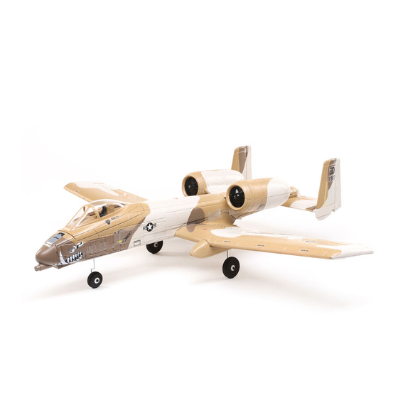
- Page 1 A-10 Thunderbolt II ™ Instruction Manual Bedienungsanleitung Manuel d’utilisation Manuale di Istruzioni...
- Page 2 Do not use with incompatible components or alter this product in any way outside of the instructions provided by Horizon Hobby, LLC. This manual contains instructions for safety, operation and maintenance. It is essential to read and follow all the instructions and warnings in the manual, prior to assembly, setup or use, in order to operate correctly and avoid damage or serious injury.
-
Page 3: Table Of Contents
Table of Contents Transmitter Setup ..........4 Motor Service .............13 Binding ..............4 Post Flight Checklist ...........14 Integrated Telemetry ..........4 Replacement Parts ..........14 ESC/Receiver Arming, Battery Installation and Recommended Items ..........14 Center of Gravity ...........5 Optional Items ............14 SAFE® Select Technology ........6 Troubleshooting Guide ........15 Control Centering ..........7 Troubleshooting Guide (Continued) ......16... -
Page 4: Transmitter Setup
Transmitter Setup IMPORTANT: After you set up your model, always Computerized Transmitter Setup rebind the transmitter and receiver to set the desired DX series, NX series, iX series failsafe positions. If your transmitter allows it, enable the throttle Start all transmitter programming with a blank ACRO cut feature. -
Page 5: Esc/Receiver Arming, Battery Installation And Center Of Gravity
ESC/Receiver Arming, Battery Installation and Center of Gravity NOTICE: Always keep material or debris away from the intake. When armed, the rotor will turn in response to throttle movement and could ingest loose objects. The UMX A-10 requires a 3S 850mAh Li-Po battery with an IC2 or EC2 connector (SPMX8503S30 recommended). -
Page 6: Safe® Select Technology
SAFE® Select Technology When SAFE Select is activated, bank and pitch limitations keep you from over-controlling the aircraft. Additionally, by releasing the controls in the event you lose orientation, SAFE Select will keep the aircraft level. To activate SAFE Select, flip the Gear channel switch to position 0. Return the Gear switch to position 1 to ®... -
Page 7: Control Centering
Control Centering Before the first flights, or in the event of an accident, make sure the flight control surfaces are centered. Adjust the linkages mechanically if the control surfaces are not centered. Use of the transmitter sub-trims may not correctly center the aircraft control surfaces due to the mechanical limits of linear servos. -
Page 8: Landing Gear Removal
Landing Gear Removal The landing gear may be left installed or removed to suit your flying area. We recommend using the landing gear when you can take off and land from a smooth surface. If you have long grass you may choose to remove the landing gear, in which case you will need to hand launch the aircraft and belly land. -
Page 9: Control Direction Test
Control Direction Test You should bind your aircraft and Transmitter Aircraft Reaction transmitter before doing these tests. Command Move the controls on the transmitter to Down make sure the aircraft control surfaces Elevator move correctly and in the proper direction. Make sure the tail linkages move freely and that paint or decals are not adhered to them. -
Page 10: As3X Direction Test
AS3X Direction Test Aircraft You should bind your aircraft and AS3X Reaction movement transmitter before doing these tests. Move the controls on the transmitter to make sure the aircraft control surfaces move correctly and in the proper direction. Make sure the tail linkages move freely and that paint or decals are not adhered to them. -
Page 11: Flying Tips And Repairs
Flying Tips and Repairs Range Check your Radio System Landing After final assembly, range check the radio system Always land into the wind. Fly the landing pattern with the aircraft. Refer to your specific transmitter with a slightly nose high attitude. Use throttle instruction manual for range test information. -
Page 12: Safe Select Flying Tips
SAFE Select Flying Tips When flying in SAFE Select mode the aircraft will return to level flight any time the aileron and elevator controls are at neutral. Applying aileron or elevator control will cause the airplane to bank, climb or dive. The amount the stick is moved will determine the attitude the airplane flies. -
Page 13: Motor Service
Motor Service Disassembly CAUTION: DO NOT handle the rotor or motor while the flight battery is connected. Personal injury could result. In order to access the motor connector(s) it is necessary to separate the top and bottom of the fuselage to access the receiver/ESC. The top and bottom fuselage parts are secured with glue and clear tape. -
Page 14: Post Flight Checklist
Post Flight Checklist Disconnect the flight battery from the ESC 5. Store the flight battery apart from the (Required for safety and battery life). aircraft and monitor the battery charge. Power OFF the transmitter. 6. Make note of the flight conditions and flight plan results, planning for future flights. -
Page 15: Troubleshooting Guide
Troubleshooting Guide AS3X Problem Possible Cause Solution Control surfaces not at Control surfaces may not have been Center control surfaces mechanically by neutral position when mechanically centered from factory adjusting the U-bends on control linkages transmitter controls are Aircraft was moved after the flight battery Disconnect and reconnect the flight battery at neutral was connected and before sensors... -
Page 16: Troubleshooting Guide (Continued)
What this Warranty Covers OTHER THAN THE EXPRESS WARRANTY ABOVE, HORIZON MAKES NO OTHER WARRANTY OR Horizon Hobby, LLC, (Horizon) warrants to the REPRESENTATION, AND HEREBY DISCLAIMS ANY original purchaser that the product purchased (the AND ALL IMPLIED WARRANTIES, INCLUDING, “Product”) will be free from defects in materials and... - Page 17 Horizon reserves the right to inspect any and all that provides tracking and insurance for lost or Product(s) involved in a warranty claim. Service or damaged parcels, as Horizon is not responsible for replacement decisions are at the sole discretion merchandise until it arrives and is accepted at our of Horizon.
-
Page 18: Warranty And Service Contact Information
800-338-4639 Horizon Technischer Service service@horizonhobby.de Hanskampring 9 European Union D 22885 Barsbüttel, Sales: Horizon Hobby GmbH +49 (0) 4121 2655 100 Germany FCC Information Contains FCC ID: BRWWACO1T the instructions, may cause harmful interference to radio communications. However, there is no Supplier’s Declaration of Conformity... -
Page 19: Eu Information
EU Compliance Statement: UMX A-10 Horizon Hobby, LLC Thunderbolt II EDF (EFLU6550) Hereby, 2904 Research Road Horizon Hobby, LLC declares that the device Champaign, IL 61822 USA is in compliance with the following: EU Radio Equipment Directive 2014/53/EU; EU Importer of Record: RoHS 2 Directive 2011/65/EU;... - Page 20 © 2021 Horizon Hobby, LLC. E-flite, AS3X, UMX, DSM, DSM2, DSMX, ModelMatch, Bind-N-Fly, EC2, IC2, IC3 and the Horizon Hobby logo are trademarks or registered trademarks of Horizon Hobby, LLC. The Spektrum trademark is used with permission of Bachmann Industries, Inc.
Need help?
Do you have a question about the UMB A-10 Thunderbolt II and is the answer not in the manual?
Questions and answers