Table of Contents
Advertisement
Available languages
Available languages
Quick Links
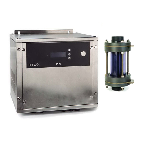
CLORADOR SALINO
SALT WATER CHLORINATOR
PRO200 / PRO250 / PRO500 /
PRO750 / PRO1000
Manual DE USUARIO
USER MANUAL
1 / 78
Manual PRO v.3
Advertisement
Table of Contents

Related Manuals for BSV PRO200


Summary of Contents for BSV PRO200
- Page 1 CLORADOR SALINO SALT WATER CHLORINATOR PRO200 / PRO250 / PRO500 / PRO750 / PRO1000 MANUAL DE USUARIO USER MANUAL 1 / 78 Manual PRO v.3...
- Page 2 Español ………………………………………….3 English …………………………………………40 2 / 78 Manual PRO v.3...
- Page 3 ANOTE EN LA SIGUIENTE FICHA LOS DATOS DE MATRICULA DEL EQUIPO QUE HA ADQUIRIDO Y QUE SE ENCUENTRAN EN LA ETIQUETA LATERAL DEL MISMO. ESTOS DATOS LE SERAN DE UTILIDAD SI DESEA REALIZAR ALGUNA CONSULTA A SU PROVEEDOR O A BSV ELECTRONIC S.L. MODELO……………………………………………… REF. ………………………………………………….. TENSION……………………………………………..
- Page 4 ÍNDICE 1- DESCRIPCIÓN GENERAL ........................... 5 1.1 Equipos de cloración salina BSV ......................5 1.2- CARACTERÍSTICAS TÉCNICAS ........................ 6 2- PREPARACIÓN DE LA PISCINA ......................... 7 2.1- Incorporación de sal en el agua ......................7 2.2 Equilibrio químico del agua ........................
- Page 5 Antes de instalar el clorador salino, lea detenidamente este manual. Si necesita alguna aclaración o tiene alguna duda póngase en contacto con su distribuidor o directamente con BSV ELECTRONIC S.L. Estaremos encantados de atenderle. 1- DESCRIPCIÓN GENERAL 1.1 Equipos de cloración salina BSV Le agradecemos la confianza al adquirir nuestro clorador salino BSPOOL, el cual le permitirá...
- Page 6 1.2- CARACTERÍSTICAS TÉCNICAS 1.2.1- TABLA CARACTERÍSTICAS PRO200 Modelos PRO250 PRO500 PRO750 PRO1000 Tensión 230Vac 230Vac 230Vac 230Vac 230Vac alimentación 50/60Hz 50/60Hz 50/60Hz 50/60Hz 50/60Hz Producción 1000 cloro g/hora Potencia 1350W 1750W 3500W 5250W 7000W máx. Corriente 45ª célula Medidas Peso...
- Page 7 Asegure la correcta ventilación del equipo Los equipos BSV PRO integran sistemas de protección contra cortocircuito en la célula, detección de falta de agua y otros sistemas de seguridad que mostrarán una señal acústica y luminosa en caso de que se produzca una anomalía.
- Page 8 Es aconsejable añadir sal a la piscina de forma progresiva, en 2 ó 3 veces para no excederse de la cantidad recomendada; un exceso de sal podría sobrecargar el clorador con lo que se desconectaría automáticamente, en cuyo caso se debería agregar agua para disminuir la concentración.
- Page 9 3- INSTALACIÓN DEL EQUIPO 3.1- Consideraciones generales: • Sitúe la célula de cloración en la posición más elevada posible del circuito de depuración y siempre después del filtro. • Si resulta posible, se recomienda la instalación de un by-pass con la célula de electrólisis con sus correspondientes llaves de paso.
- Page 10 Instalación recomendada (PRO250) 1. FILTRACIÓN 2. CUADRO ELÉCTRICO 3. SENSOR DE FLUJO 4. CÉLULA ELECTRÓLISIS 5. EQUIPO PRO250 Instalación recomendada (PRO750) 10 / 78 Manual PRO v.3...
- Page 11 Ofrece una baja dependencia del pH y de la concentración de ácido isocianúrico, así como la posibilidad de instalarse en piscinas de agua de mar (opción que debe solicitar previamente a BSV Electronic). Por favor, siga cuidadosamente las instrucciones de instalación, calibración y mantenimiento para asegurar un perfecto funcionamiento del kit.
- Page 12 3.2.2.1.2-Sonda de Cloro Libre: Este kit incluye: Sonda CC1 Membrana (incorporada en el cabezal) Tapón protector superior Electrolito ECC1.1/GEL Papel Abrasivo 3.2.2.2- Características técnicas CARACTERÍSTICAS TÉCNICAS Cloro libre, con baja dependencia de pH. Contenido máximo de Medida isocianuratos: 500mg/l Tecnología Sistema de membrana, cabezal potenciostático de 3 electrodos.
- Page 13 3.2.2.3- Instalación Por favor, siga atentamente las recomendaciones relativas a la instalación de la sonda para garantizar el buen funcionamiento de la misma. 3.2.2.3.1 Instalación hidráulica Instale el portasondas fijándolo a la pared mediante los tornillos y tacos incluidos en la caja. Asegúrese de que la sonda queda bien nivelada. Tal y como se observa en la siguiente imagen, la entrada de la muestra de agua se realiza por la parte inferior del portasondas, mientras que el retorno se efectúa a través de la salida situada en la parte superior derecha del...
- Page 14 Recomendaciones adicionales: -Siempre que sea posible, instale una llave de paso a la entrada y otra a la salida del tubo flexible para facilitar las tareas de limpieza y mantenimiento de las sondas. -La toma de agua del portasondas puede conectarse después del filtro de la piscina, aunque deberá...
- Page 15 Por favor, asegúrese de que este paso se realiza correctamente, ya que en caso contrario se destruiría la membrana del cabezal, anulando la garantía del mismo. 4) Enrosque el cabezal al cuerpo de la sonda. Tenga en cuenta que el electrolito sobrante saldrá...
- Page 16 Una vez realizada la conexión, cierre el tapón superior y apriete el prensaestopas. Conecte el cable de la sonda en la regleta la P954D, según lo indicado a continuación: o Cable Blanco: Entrada 9 o Cable Marrón: Entrada 8 o Debe realizarse un Puente entre las entradas 5 y 11. 3.2.2.3.4 Calibración 1) Instale la sonda en el portasondas.
- Page 17 3) Ponga en marcha el equipo de electrolisis / dosificación. La lectura aumentará de forma progresiva hasta estabilizarse tras unos minutos. Nota: El tiempo de estabilización de la primera puesta en marcha puede resultar ligeramente superior a la habitual. En cualquier caso, se recomienda esperar por lo menos 3 horas antes de realizar una primera calibración de la sonda.
- Page 18 b. Diríjase al menú Cloro -> Calibración. Pulse OK y espere a que la medida sea estable: c. Ajuste el valor real de la medida a partir del obtenido mediante su equipo de medida DPD-1. d. Diríjase de nuevo a la pantalla principal. Observará que la medida de cloro libre se corresponde al ajuste que acaba de realizar.
- Page 19 4) Enjuague el cabezal cuidadosamente con agua del grifo, y posteriormente rellénelo con nuevo electrolito. En caso de sustitución del cabezal, deseche el antiguo y monte uno nuevo. 5) IMPORTANTE: Antes de enroscarlo al cuerpo de la sonda, retire el anillo de silicona para destapar el orificio de ventilación.
- Page 20 (L1-L2-L3) que se muestran en la foto. En configuración monofásica, estas regletas deben ir unidas por el puente indicado por el círculo rojo: Figura 3.1: Conexión en línea monofásica Conecte el cable de tierra a la regleta correspondiente Conecte el interruptor de flujo en la posición indicada en la figura 3.2 Conexión a red Trifásica: Asegurar que la línea dispone de las protecciones y sección de cable correctamente dimensionadas al consumo del equipo (ver tabla de...
- Page 21 Figura 3.2: Conexión en línea trifásica Sincronización del clorador salino con la bomba de filtración: Existen dos opciones para alimentar el equipo, asegurando que solamente funcione cuando la filtración esté conectada. Opción A) Alimentación del equipo a través del contactor de la bomba de filtración: o Alimente el clorador salino mediante del propio contactor de la bomba.
- Page 22 o Conecte la alimentación general del equipo directamente a la línea monofásica trifásica (según como esté configurado su equipo). o Retire el Jumper LK1 para habilitar el modo paro/marcha. A través de este conexionado, el equipo habilitará la producción de cloro cuando la filtración esté...
- Page 23 Figura 3.4: Conexión a la célula de electrolisis Asegúrese de que los terminales quedan fuertemente unidos a la célula En caso de que su equipo se componga de más de una célula, siga un mismo criterio a la hora de conectar los cables (ejemplo: los cables marrones en la parte superior de las células y los azules en la inferior).
- Page 24 4- OPERACIÓN 4.1- Equipos PRO250, PRO500, PRO750, PRO1000 Los equipos PRO disponen de una pantalla LCD mediante el cual podrá visualizar y configurar todas las funciones del equipo. Menú Clorador: Menú configuración Lengua Menú principal Control Ciclo de limpieza de la célula Configuración Interruptor Caudal N (S) Cloración...
- Page 25 En la línea superior se muestra el % de producción de cada una de las fuentes que incorpore el equipo En la segunda línea se muestra la tensión de cada fuente La tercera línea muestra la lectura de la sonda de cloro libre, en caso de estar instalada.
- Page 26 ATENCION: Se le solicitará una contraseña si desea cambiar la configuración de algunas de las opciones de este menú. Esto previene al usuario de realizar cambios de forma accidental que puedan afectar al correcto funcionamiento del equipo. 4.1.2.1.1- Lengua Permite seleccionar el idioma 4.1.2.1.2- Control El equipo permite seleccionar entre 2 modos diferentes de control: Manual: El equipo produce cloro de manera continua, en función del % de...
- Page 27 Seleccione este modo si no dispone de una sonda de cloro libre, ajustando la producción y las horas de filtración en función de la naturaleza de su piscina, volumen, número de bañistas y estación del año. Automático Seleccione este modo solamente si dispone de un kit sonda Amperométrica.
- Page 28 Nota: Para modificar esta configuración, se requiere introducir la contraseña “1234”. 4.1.2.1.5- Ácido / Alcalino Esta opción le permite seleccionar el tipo de corrector de pH que va a utilizar en su piscina. Atención: Debe seleccionarlo correctamente, de no ser así, el sistema de dosificación funcionará...
- Page 29 La sonda de pH está sucia o gastada, y no lee correctamente el valor real. Sin embargo, puede ocurrir, principalmente en la puesta en marcha del sistema por primera vez, que el pH real del agua esté muy lejos de la consigna. Puede deshabilitar la alarma si se estima que la bomba necesitará...
- Page 30 NOTA: si se trabaja en automático, también podemos regular el porcentaje de producción de 0% a 100% NOTA: Únicamente el modelo PRO200 admite tanto regulación con sonda de cloro libre (ppm) y ORP. Para los modelos 250, 500, 750 y 1000, solamente se puede realizar regulación a través de sonda de...
- Page 31 Si disponemos de sonda de cloro libre, aparece un menú que permite la calibración de la misma: Una vez estabilizada la lectura y realizada la medición de cloro con DPD1, ajustar el valor de PPM que nos ha dado la medición DPD1. 4.1.2.3- Menú...
- Page 32 pH. Espere a que se estabilice la lectura y entonces espere al menos un minuto más. Pulse el botón “OK”. 4.1.2.3.3- Encendido y apagado de la regulación del pH Para apagar o volver a poner en marcha el control del pH, parando la bomba de ácido, acceda al menú...
- Page 33 4.2- Mensajes de advertencia y alarmas En caso de funcionamiento anómalo, los equipos de la serie PRO le mostrarán un mensaje de alarma en la 4ª línea de la pantalla, junto a un aviso acústico. Las alarmas detienen el equipo hasta que el problema se resuelva. Del mismo modo, mostrará...
- Page 34 4.2.2- Mensajes de Alarma En los siguientes casos el clorador se para y se activa el LED de alarma y la alarma acústica (rearme automático al cesar el fallo): “SIN FLUJO” Exceso de gas en la célula Debemos purgar la tubería para electrolítica.
- Page 35 El equipo no dispone de Instale una sonda de Redox o sonda y se encuentra en Cloro Libre, o bien configure modo “automático” seleccione el modo “manual” “Alarma pH Recipiente de ácido vacío. Rellenar tanque de dosificación Problema en la bomba o Revisar conexionado bomba en la conducción del ácido.
- Page 36 El sensor ha estado unas Dejar que circule agua que horas midiendo agua sin cloro contenga cloro libre por el libre posartsensores durante 1 hora Lectura inferior a la Caudal insuficiente en el Ajustar el caudal que llega medida DPD-1 portasensores al portasensores Limpiar el filtro y el...
- Page 37 El pH es inferior a 6.5, y por lo Ajustar el pH dentro del tanto está fuera de la zona margen de pH admisible recomendada de lectura. Lectura inestable Fallo en la conexión del Revisar conexiones sensor con el controlador Caudal de agua que llega al Estabilizar presión en la portasensores inestable, y el...
- Page 38 Debe tenerse en cuenta que todas las reparaciones en garantía se realizarán en fábrica. BSV Electronic S.L se reserva el derecho de modificación del equipo así como del manual de instrucciones sin previo aviso. Gracias por escoger el Clorador Salino BSPOOL para su piscina.
- Page 39 Anexo 1: ESQUEMA ELÉCTRICO DE MANIOBRA Y CONEXIONADO 39 / 78 Manual PRO v.3...
- Page 40 PLEASE NOTE IN THE FOLLOWING CARD THE REGISTRATION DATA OF THE EQUIPMENT YOU HAVE PURCHASED, WHICH ARE FOUND ON THE SIDE LABEL. THESE DATA WILL BE OF USE IF YOU WISH TO MAKE ANY ENQUIRY TO YOUR SUPPLIER OR TO BSV ELECTRONIC S.L. MODEL……………………………………………… REF. ………………………………………………….. VOLTAGE……………………………………………..
- Page 41 INDEX 1- GENERAL DESCRIPTION ......................... 42 1.1- BSV PRO salt water chlorination equipment ..................42 1.2- Technical specifications ........................43 1.3- Recommendations and safety precautions ..................43 2- PREPARING THE SWIMMING POOL ...................... 44 2.1- Adding salt to the water ........................
- Page 42 Before installing the salt water chlorinator, please read this manual carefully. If you need to clarify any point or have any doubts, please contact your dealer or BSV ELECTRONIC S.L. directly. We will be delighted to assist you. 1- GENERAL DESCRIPTION 1.1- BSV PRO salt water chlorination equipment...
- Page 43 1.2- Technical specifications 1.2.1- Equipment PRO200 Models PRO250 PRO500 PRO750 PRO1000 Supply 230Vac 230Vac 230Vac 230Vac 230Vac voltage 50/60Hz 50/60Hz 50/60Hz 50/60Hz 50/60Hz Chlorine production 1000 g/hour Max. power 1350W 1750W 3500W 5250W 7000W Cell current Dimensions Weight 15Kg 20Kg...
- Page 44 Ensure that the heatsink wings are not blocked and that air can easily circulate through them. BSV PRO equipment incorporate protection systems against short circuits in the cell, absence of water detector and other safety systems that give an acoustic and visual alarm in the event of any anomaly. However, for optimum results, you should ensure the correct hydraulic operation of your swimming pool.
- Page 45 We recommend using salt that is especially prepared for use in salt water chlorination installations, as it is especially prepared for rapid dissolution and to achieve optimum results. You can find it at retailers specializing in swimming pool products. ATTENTION When adding salt to the swimming pool, first disconnect the chlorinator (position OFF), and start-up the filter for 3 or 4 hours, in order for the salt to dissolve and not to overload the equipment.
- Page 46 AMMONIA (mg/l) <0.3 IRON (mg/l) <0.3 COPPER (mg/l) <1.5 ALKALINITY (mg/l) CONDUCTIVITY (us/cm) <1700 TDS (mg/l) <1000 HARDNESS (mg/l) 3- INSTALLATION OF THE EQUIPMENT 3.1- General considerations: • Place the chlorination cell in the highest position possible of the purification circuit and always after the filter.
- Page 47 3.2- Hydraulic connection diagram 3.2.1- Diagram Electrolisys cell Recommended installation (PRO250) 1. FILTRATION 2. CONTROL PANEL 3. FLOW SWITCH 4. ELECTROLYSIS CELL 5. PRO250 UNIT(*) 47 / 78 Manual PRO v.3...
- Page 48 (this option to be asked to BSV Electronic). Please follow carefully the installation, calibration and maintenance instructions to ensure a perfect setup of the kit.
- Page 49 3.2.2.1 – Kit content 3.2.2.1.1- Probe Holder 3.2.2.1.2- Free Chlorine Probe Includes CC1 Probe Membrane (Included in the header) Protection cap ECC1.1/GEL Electrolyte Abrasive paper 49 / 78 Manual PRO v.3...
- Page 50 Operation maximum pressure 0.5 bar. Water hammer effect must be avoided. pH range 4 to 12 Calibration Directly on BSV control panel Maximum time without CL on water Water test: Minimum once a week Header-membrane change: Once a year Maintenance period...
- Page 51 Additional recommendations: - If possible, install a hose valve at input, and another one at output to ease the cleaning and maintenance tasks. -The probe holder water inlet can be connected after the filter, but then a good maintenance of the filter cleaning must be ensured, otherwise the measure can be affected by the chlorine consumption inside the filter.
- Page 52 3) Caution: Before screwing again the header cap to the sensor body, the silicone ring must be removed, uncovering the small hole shown in the following picture: Please, take care that this step is done correctly, otherwise the header membrane could be damaged, and will be out of warranty. 4) Screw the header cap to the body of the probe.
- Page 53 3.2.2.3.3 Electrical connection Before installing the probe on the probe holder, connect the supplied cable as follows: Connect the white cable to the (+) input, it has a red or blue mark in the right side. Connect the dark cable to the (-) input. Once the connection is done, screw the cap and the cable gland.
- Page 54 Connect the cable to the P954D as follows: o White cable: Input 9 o Dark cable: Input 8 o A cable bridge must be done between inputs 5 and 7. 3.2.2.3.4 Calibration 1) Install the probe on the probe holder. Use a tool to ensure the sensor is correctly tightened.
- Page 55 3) Switch on the electrolysis / dosing System. The CL reading will slowly increase and will be stable after some minutes. Note: When the probe is switched on for the first time, the stabilization time could take longer than usual. In any case, it is recommendable to wait for at least 3 hours before making a first calibration.
- Page 56 b. Chlorine Menu -> Select “calibration” and press OK. Wait until the reading is stable: c. Adjust the real value obtained by means of DPD-1 test. d. Return to the main screen. The current CL value will match with the value obtained from DPD-1 test. 3.2.2.3.5 Probe maintenance Please, carefully read the following maintenance instructions for your PRO/2 Kit.
- Page 57 4) Carefully wash the header with tap water, and fill it again with new electrolyte. In case of the header needs to be replaced, discard the used an install a new one. 5) Remove the silicone ring, uncovering the small hole. 6) Completely screw the header, cleaning the excess of electrolyte, and place again the silicone ring to its place.
- Page 58 In single-phase configuration, the three phase strips must be connected together by means of a connection bar (see the following picture marked with a red circle): Figura 3.1: Single-phase connection Connect the earth cable to the corresponding strip. Connect the flow switch to the position shown at 3.3 figure. Connection to the three-phase line: Ensure the line supply has all the protections and the correct cable size according with the current consumption (see table on page 32)
- Page 59 Figure 3.2: Three-phase connection Synchronization of the unit with the filtration pump: There are two options to ensure that the chlorination works only when the filtration pump is on: Option A) Line supply by means of the filtration pump contactor: o Connect the chlorinator’s input line directly to the filtration pump contactor o Ensure that the contactor is correctly sized to be able to...
- Page 60 Connect the input line of the chlorinator directly to the mains (single-phase or three-phase) depending on how it’s been configured. o Remove the LK1 jumper to enable the start/stop mode. Whith this configuration, the chlorinator will start the chlorine production when the filtration pump is on, and will stop it when it’s off while a “stop”...
- Page 61 Ensure all the cables are tightly connected with the cell. In case that the unit has two or more cells, it is advisable to follow the same rule for all the cell connections (for example: all the brown cables at the upper side of all the cells, and the blue cables to the down side). 61 / 78 Manual PRO v.3...
- Page 62 4- OPERATION 4.1- PRO250, PRO500, PRO750, PRO1000 units The SMART series equipment has an LCD screen, in which you can view and configure all operations of the equipment. The following table shows how to organize the configuration menu of the equipment: Chlorinator Menu Configuration menu Main menu...
- Page 63 4.1.1- Main screen On starting up the equipment, a screen will be displayed with the main parameters. En la línea superior se muestra el % de producción de cada una de las fuentes que incorpore el equipo En la segunda línea se muestra la tensión de cada fuente La tercera línea muestra la lectura de la sonda de cloro libre, en caso de estar instalada.
- Page 64 Using the buttons you can select a line of the menu, indicated by the arrow (→). The OK button is used to confirm the selection. To access the configuration menu, you need to confirm the operation by selecting (S) through the arrow, and pressing OK. 4.1.2.1- Configuration In the configuration menu you can select the configuration parameters, which usually only have to be adjusted when installing the equipment.
- Page 65 4.1.2.1.1- Language From the configuration menu select "Language", press the OK button, and once the required language has been selected, press the OK button and EXIT. 4.1.2.1.2- Control The equipment allows you to select from 2 different modes of control: Manual: The equipment produces chlorine continuously, depending on the % of production selected.
- Page 66 4.1.2.1.3- Cleaning The equipment includes an automatic cleaning system, based on reversing polarity in the electrolysis cell. These cleaning cycles are performed regularly. The time between cleaning (in hours) can be adjusted depending on the water hardness of your swimming pool. It is possible to select cleaning intervals from 1 to 8 hours.
- Page 67 4.1.2.1.5 Acid / Alkali With this option you can select the type of pH corrector to be used in your swimming pool. Attention: It should be selected correctly otherwise the dosing system will work opposite to expected. Acid: Select this mode if you are going to inject pH reducer into the swimming pool (default mode).
- Page 68 4.1.2.1.7 Chlorine/ORP Alarm When the unit is configured in automatic mode, it is possible to disable the “Chloride Alarm”. This alarm will detect if the ORP or PPM reading hasn’t changed for two hours or more, despite the unit has been in production. Despite this alarm is been implemented to detect if a probe is not in good conditions, or there is some chemical issue in the water, it can be disabled if the user wants to maintain the production despite everything.
- Page 69 NOTE: if working in automatic, you can also adjust the production percentage from 0% to 100%, NOTE: PRO200 model is the only one which ORP and Free Chlorine regulation is available. Free Chroline regulation is only allowed in PRO250, 500, 750 and 1000.
- Page 70 4.1.2.3.1- pH Adjustment Go to the main menu, select "pH" and in the pH menu that is displayed, select “pH +-” Use the buttons to adjust the required pH and confirm with "OK". 4.1.2.3.2- Calibration of the pH probe To calibrate the probe, prepare a glass with clean water.
- Page 71 4.1.2.4- Clock The equipment has a time clock, which will be taken as the reference when programming times of the auxiliary relay. The clock keeps the time setting even when the equipment is without supply. 71 / 78 Manual PRO v.3...
- Page 72 4.2- Warning message and alarms In the event of abnormal operation, the SMART series equipment will display an alarm message on the 4th line of the screen, together with an acoustic warning. The alarms shutdown the equipment until the problem is solved. Similarly, it will display a warning also in the 4th line, but without an acoustic signal or shutting down the equipment.
- Page 73 In the following cases, the chlorinator shuts down and the alarm and acoustic alarm LED is activated (automatic reset once the fault is solved): "NO WATER Excess The piping should be drained to FLOW" electrolysis cell. It may eliminate gas or accumulated have occurred because the water.
- Page 74 “pH Alarm” Empty dosing tank Fill up dosing tank pH pump problem Check wiring connections Probe or cable damaged Put it into pattern liquid. Check if probe is working 4.3- Working hours It may be useful to see the operation times for regular maintenance operations. From the main screen, press both buttons ...
- Page 75 measuring zone of the sensor that there is no air remaining in the measuring zone. The sensor has been a number of hours measuring Let water containing free chlorine the water without free circulate through the sensor holders for chlorine 1 hour.
- Page 76 Repeat the DPD-1 measurement with DP-! Reactives are worn new reactives DPD-1 measurement is Increase the waiting time in the incorrect owing to a sample reaction of the DPD measurement of water with high salinity reactives. Failure in sealing of the sensor Check sealing rings of the sensor The pH of the water is lower...
- Page 77 The pH is unstable Stabilize the pH. 6- WARRANTY AND SERVICE BSV Electronic S.L. guarantees its BSPOOL equipment for a period of 2 years in control centres. The electrolysis cells have a control of two years, as long as they have not exceeded 10,000 hours of use.
- Page 78 Annex 1: Electrical connection schematic 78 / 78 Manual PRO v.3...
Need help?
Do you have a question about the PRO200 and is the answer not in the manual?
Questions and answers