
Subscribe to Our Youtube Channel
Related Manuals for BSV PRO50


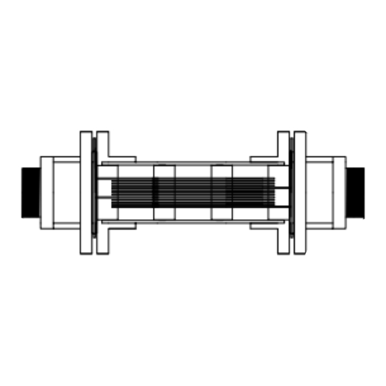
Summary of Contents for BSV PRO50
- Page 1 CLORADOR SALINO SALT WATER CHLORINATOR PRO50 / PRO70 / PRO100 / PRO150 MANUAL DE USUARIO USER MANUAL Manual PRO50-150 V.6 1 / 72...
- Page 2 Español English INDICE Manual PRO50-150 V.6 2 / 72...
- Page 3 2.2 Equilibrio químico del agua 3- INSTALACIÓN DEL EQUIPO 3.1- Consideraciones generales 3.2- Esquema de conexionado hidráulico 3.2.1- Equipos de la serie PRO50-70 3.2.2- Equipos de la serie PRO100-150 3.2.3- Kit AUTO 3.2.4- Kit ADVANCED (Redox) (OPCIONAL) 3.2.5- Kit PRO/2 (Cloro libre) (OPCIONAL) 3.2.6- Kit sonda NTC/1 (OPCIONAL)
- Page 4 (de 8 a 15 en función del uso), colaborando así con las políticas de conservación del medio ambiente y a la gestión y ahorro del agua. Manual PRO50-150 V.6 4 / 72...
- Page 5 Desconecte el equipo de la red antes de realizar cualquier operación de montaje o mantenimiento. Asegúrese de que la instalación eléctrica dispone de los elementos de protección obligatorios (magnetotérmico y diferencial) y que éstos funcionan correctamente. Manual PRO50-150 V.6 5 / 72...
- Page 6 Los equipos BSV integran sistemas de protección contra cortocircuito en la célula, detección de falta de agua y otros sistemas de seguridad que mostrarán una señal acústica y luminosa en caso de que se produzca una anomalía.
- Page 7 OZONO (vaso) (mg/l) OZONO (antes de) TURBIDEZ (NTU) <1 OXIDABILIDAD (mg/l) <3 NITRATOS (mg/l) <20 AMONIACO (mg/l) <0,3 HIERRO (mg/l) <0,3 COBRE (mg/l) <1,5 ALCALINIDAD (mg/l) CONDUCTIVIDAD (us/cm) <1700 TDS (mg/l) <1000 DUREZA (mg/l) Manual PRO50-150 V.6 7 / 72...
- Page 8 3- INSTALACIÓN DEL EQUIPO 3.1- Consideraciones generales En los modelos PRO50 y PRO70, colocar la célula de cloración en posición vertical con las conexiones eléctricas hacia arriba. De no ser posible, pude montarse en posición horizontal, cuidando que el pequeño electrodo auxiliar situado hacia arriba.
- Page 9 3.2- Esquema de conexionado hidráulico 3.2.1- Equipos de la serie PRO50-70 1. De la piscina. 2. Filtración. 3. Cuadro eléctrico. 4. Bypass. 5. Flow Switch (Opcional). 6. Sonda de temperatura (Opcional). 7. Sonda de pH, incluida en el kit Auto (Opcional) 8.
- Page 10 10. Inyector de ácido. Mantener el recipiente de ácido lo más alejado posible del equipo. 11. Clorador PRO 12. Célula electrolisis 13. Bomba de pH 14. Sistema domótico KIT CONNECT (Opcional) 15. A la piscina. Manual PRO50-150 V.6 10 / 72...
- Page 11 Una vez instaladas las células, conecte los cables, uno a cada extremo de la célula, utilizando la tornillería que se incluye con el equipo. Asegúrese de que los terminales quedan fuertemente unidos a la célula Manual PRO50-150 V.6 11 / 72...
- Page 12 8- Inyector (colocar con la flecha hacia abajo) 9- Racor conversión 3/8,1/2 10-Brida (No incluida) 11-Entrada ácido (tubo aspiración) 12-Salida ácido (tubo inyección) 13-Conector sonda pH (BNC) 14-Líquido calibración pH4 15-Líquido calibración pH7 16-Tapon goma para calibración Manual PRO50-150 V.6 12 / 72...
- Page 13 10- Colocar el porta-sonda (6) dentro de la brida (7). 11- Colocar la sonda de PH (5) dentro del porta-sonda (6). 12- Colocar el conector de la sonda de PH (5) en el conector BNC (13) del equipo. Manual PRO50-150 V.6 13 / 72...
- Page 14 ácido isocianúrico, así como la posibilidad de instalarse en piscinas de agua de mar (opción que debe solicitar previamente a BSV Electronic). Por favor, siga cuidadosamente las instrucciones de instalación, calibración y mantenimiento para asegurar un perfecto funcionamiento del kit.
- Page 15 3.2.7- Lectura de concentración de sal en los equipos PRO (solo en PRO50 y PRO70) En caso de haber instalado un kit sonda NTC/1 en su equipo (esquema en página 2), se le habilitará la función de lectura de concentración de sal en el agua.
- Page 16 3.3- Esquema de conexionado eléctrico 3.3.1- Equipos serie PRO50/70 Conexión tierra L, N: Alimentación 220v Interruptor Encendido / Apagado Conexión bomba de pH (Sólo en modelos con kit AUTO) R.AUX: Relé auxiliar FILTER: Conexión filtro para el modo Paro / Marcha Regleta conexión célula...
- Page 17 12-(gris) blanco ) Interruptor FLOW externo (5-6)* 13-(verde) azul) Sonda Temperatura 14-(rojo) *activar la función FLOW SWITCH en menú de configuración K1: Relé PH K4: Relé auxiliar LK2: Paro/Marcha (ver apartado 3.3.2.1) F1: Fusible Manual PRO50-150 V.6 17 / 72...
- Page 18 Para activar este modo de funcionamiento debe retirar el puente “LK2” de la placa de potencia, alimentar el clorador directamente a 230V, y conectar las entradas “filtro” en paralelo a la alimentación de la bomba de filtración. Manual PRO50-150 V.6 18 / 72...
- Page 19 Atención: No superar nunca los 16A cuando utilice el relé auxiliar. Para corrientes mayores, complemente el circuito con un contactor. Tenga en cuenta que el relé es libre de potencial, por lo que deberá alimentar el circuito externamente. Manual PRO50-150 V.6 19 / 72...
- Page 20 Puede controlar la bomba de filtración a través del relé auxiliar siguiendo el esquema siguiente: Debe tenerse en cuenta que el equipo debe configurarse en modo “paro- marcha”, tal y como se detalla en la 3.3.2.1. Manual PRO50-150 V.6 20 / 72...
- Page 21 4- PUESTA EN MARCHA Y AJUSTES Una vez haya instalado el clorador salino BSV puede poner en marcha su equipo de cloración salina. Siga con atención las instrucciones, en los apartados siguientes se detalla el funcionamiento de los diferentes modelos existentes: 4.1- Equipos serie PRO...
- Page 22 La tercera línea muestra la lectura del pH. La 4ª línea muestra Menú (pulsando el botón OK se accede al menú) y la hora del reloj. Además, si se produce cualquier alarma o advertencia, esta será mostrada también en esta línea. Manual PRO50-150 V.6 22 / 72...
- Page 23 ATENCION: Se le solicitará una contraseña si desea cambiar la configuración de algunas de las opciones de este menú. Esto previene al usuario de realizar cambios de forma accidental que puedan afectar al correcto funcionamiento del equipo. Manual PRO50-150 V.6 23 / 72...
- Page 24 Tenga en cuenta que el equipo efectúa un cálculo aproximado del cloro que debe producir a partir de dos parámetros conocidos. Sin embargo, no se tiene en cuenta otros factores como el consumo de cloro provocado por el número de bañistas diarios. Manual PRO50-150 V.6 24 / 72...
- Page 25 Al poner la cubierta, el clorador baja automáticamente su producción situándola al 20%. Dicha variación se verá reflejada en el % de producción, y se mostrará el carácter “C” a la derecha de la producción en la pantalla principal. Esto nos indicará que la cubierta está activada. Manual PRO50-150 V.6 25 / 72...
- Page 26 Para activar el sensor de flujo, deberemos disponer del “Kit Flow” (opcional) y activarlo en el menú seleccionando el modo Flow Switch= Y. Nota: Para modificar esta configuración, se requiere introducir la contraseña “1234”. Manual PRO50-150 V.6 26 / 72...
- Page 27 Si bien esta alarma le permite detectar que una sonda se encuentra en mal estado o bien existe un desequilibrio en la química del agua, puede suprimirse si a pesar de todo, no quiere que la producción se detenga bajo estas circunstancias. Esta alarma viene desactivada de fabrica Manual PRO50-150 V.6 27 / 72...
- Page 28 NOTA: si se trabaja en automático, también podemos regular el porcentaje de producción de 0% a 100% Manual PRO50-150 V.6 28 / 72...
- Page 29 La lectura de la sonda de pH puede observarse en la 3ª línea de la pantalla principal. La regulación del pH no se pone en marcha hasta pasados 5 minutos después de que se encienda el equipo. Manual PRO50-150 V.6 29 / 72...
- Page 30 Una vez transcurridos los 60 segundos, limpie la sonda y sumergala en la solución patrón de pH4 y pulse OK. Espere 60 segundos; el display indica el valor medido de pH4 Manual PRO50-150 V.6 30 / 72...
- Page 31 Los equipos de la serie PRO disponen de un relé auxiliar programable, que puede utilizar para controlar la bomba de filtración, iluminación de su piscina, entre otros. Puede ver más detalles en las páginas 30 y 31 de este manual. Manual PRO50-150 V.6 31 / 72...
- Page 32 4.1.8- Reloj El equipo dispone de un reloj horario, que se tomará como referencia en la programación horaria del relé auxiliar. El reloj conserva el ajuste de la hora aunque el equipo permanezca sin alimentación. Manual PRO50-150 V.6 32 / 72...
- Page 33 Dejar reposar el equipo unos minutos. Consultar apartado número 4. Instalación. Las aletas del radiador están Colocar el equipo de forma que tenga obstruidas o no están en circulación de aire para una correcta posición vertical. refrigeración Manual PRO50-150 V.6 33 / 72...
- Page 34 “Alarma cl.” Sonda de cloro mal Comprobar el cableado de la sonda y conectada o averiada la misma sonda. Ver 5.1. En caso de necesidad puede trabajarse en modo manual. Manual PRO50-150 V.6 34 / 72...
- Page 35 Si después de proceder a su limpieza, el equipo no trabaja normalmente, se deberá sustituir la sonda o célula. En cualquier caso, su distribuidor puede orientarle sobre la necesidad de cambiar estos elementos. Manual PRO50-150 V.6 35 / 72...
- Page 36 Si una sonda se ha dejado secar puede regenerarse dejándola unas 12 horas en un vaso de agua, preferiblemente añadiéndole unas gotas de ácido clorhídrico. 5.4- Comprobación y mantenimiento de la sonda Amperométrica (kit PRO/2) Ver manual adjunto en el Manual PRO50-150 V.6 36 / 72...
- Page 37 En el caso de que falle el equipo se deberá devolver al fabricante o distribuidor. Los gastos de envío correrán a cargo del propietario del equipo. Debe tenerse en cuenta que todas las reparaciones en garantía se realizarán en fábrica, o bien por un servicio técnico autorizado por BSV Electronic. Manual PRO50-150 V.6 37 / 72...
-
Page 38: Table Of Contents
2.1- Adding salt to the water 2.2 Chemical balance of the water 3. INSTALLATION OF THE EQUIPMENT 3.1- General considerations 3.2- Hydraulic connection diagram 3.2.1- PRO50-70 Series Equipment 3.2.2- PRO100-150 Series Equipment 3.2.3- AUTO kit 3.2.4- ADVANCED kit (Redox) (OPTIONAL) 3.2.5- PRO kit (OPTIONAL) 3.2.6- NTC/1 kit (OPTIONAL) -
Page 39: 1- General Description
If the salt water chlorinator equipment is left to work permanently, it will not be necessary to change the swimming pool water for several years (8 to 15 depending on its use). You will therefore, be collaborating with environment preservation policies and water management and saving. Manual PRO50-150 V.6 39 / 72... -
Page 40: Technical Specifications
Make sure that the electrical installation has all compulsory protection elements (circuit breaker and differential switch) in perfect condition. It is important to ensure that the supply cables of the electrolysis cell are tightly connected, otherwise the equipment could overheat and break down. Manual PRO50-150 V.6 40 / 72... -
Page 41: 2- Preparing The Swimming Pool
Ensure that the heatsink wings (in the rear part of the equipment) are not blocked and that air can easily circulate through them. All the BSV equipment incorporate protection systems against short circuits in the cell, absence of water detector and other safety systems that give an acoustic and visual alarm in the event of any anomaly. -
Page 42: Chemical Balance Of The Water
<75 OZONE (GLASS) (mg/l) OZONE (before) TURBIDITY (NTU) <1 OXIDES (mg/l) <3 NITRATES (mg/l) <20 AMMONIA (mg/l) <0.3 IRON (mg/l) <0.3 COPPER (mg/l) <1.5 ALKALINITY (mg/l) CONDUCTIVITY (us/cm) <1700 TDS (mg/l) <1000 HARDNESS (mg/l) Manual PRO50-150 V.6 42 / 72... -
Page 43: Installation Of The Equipment
A good earth connection is essential. Use a differential relay with max. 30mA of sensitivity. If a good quality earth connection is not available, place an earth connection kit between the electrolysis cell and the redox probe. OPTIONAL KIT Manual PRO50-150 V.6 43 / 72... -
Page 44: Hydraulic Connection Diagram
3.2- Hydraulic connection diagram 3.2.1- PRO50-70 Series Equipment 1. From the swimming pool. 2. Filtration 3. Electrical Panel 4. Bypass 5. Flow Switch (optional) 6. Conductivity probe (optional) 7. Temperature probe (optional) 8. pH probe, included in AUTO kit (optional) 9. -
Page 45: 2- Pro100-150 Series Equipment
8. pH probe, included in AUTO kit (optional) 9. Redox probe, included in ADVANCED kit (optional) 10. Ground kit (optional) 11. Acid injector 12. PRO50-70 chlorinator 13. Electrolysis cell 14. pH pump 15. Domotic CONNECT kit (optional) 16. To the swimming pool. - Page 46 Connecting the cells to the unit Once the cells are installed, connect the cables to each side of the cell, using the provided nuts and bolts. Verify that the cable terminals are tightly connected to the cell. Manual PRO50-150 V.6 46 / 72...
-
Page 47: 3- Auto Kit
9. Pipe nipple 3/8,1/2 10. Flange 11. Acid inlet (suction tube) 12. Acid outlet (injection tube) 13- pH probe connector (BNC) 14- pH4 calibration liquid 13. pH7 calibration liquid 14. Rubber cap for calibration Manual PRO50-150 V.6 47 / 72... - Page 48 9- Connect the other end of the injection tube (3) to the injector (8). 10- Place the probe holder (6) inside the flange (7). Place the PH probe (5) inside the probe holder (6). Place the PH probe (5) connector in the BNC connector (13) of the equipment. Manual PRO50-150 V.6 48 / 72...
-
Page 49: 4- Advanced Kit (Redox) (Optional)
This ppm measure has a low dependency of pH and isocyanuric acid, and it can be also installed in sea water swimming pools (this option to be asked to BSV Electronic). Please follow carefully the installation, calibration and maintenance instructions to ensure a perfect setup of the kit. - Page 50 Important: Salt concentration measurements are trustworthy only if the cell is in good conditions. If the cell is worn out or with overlay, the value displayed could differ from the actual salt concentration in the water. Manual PRO50-150 V.6 50 / 72...
-
Page 51: Electrical Wiring Diagram
3.3- Electrical wiring diagram 3.3.1- PRO50/70 units Earth connection L, N: Supply 220v On / Off Switch pH pump connection (For units with the AUTO kit) AUX R: Auxiliary relay FILTER: Filter connection for Stop / Start mode Terminal block of cell... -
Page 52: 2- Pro100/150 Units
2-Acid level sensor (PH) 9-ORP- 3-Cover 10-ORP+ 4-Cover 5-Flow sensor (cable 1) 6-12V for the flow switch (between 5-6)* 7-Temperature probe *Activate the flow switch function in the configuration menu J31: Start/Stop (See section 3.3.3.1) F1: Fuse Manual PRO50-150 V.6 52 / 72... -
Page 53: 3- Advanced Functions
V, and connect the "filter" inlets in parallel to the supply of the filtering pump. In this way, when the filtration pump turns on, the “filter” input must be connected to 220V, and when the pump stops, “filter” input connector must be at 0V. Manual PRO50-150 V.6 53 / 72... - Page 54 Attention: Never exceed 12A when using the auxiliary relay. For higher currents, supplement the circuit with a contactor. Remember that the relay is potential free, and therefore the circuit should be supplied externally. Manual PRO50-150 V.6 54 / 72...
- Page 55 3.3.3.3- Filtering control through the auxiliary relay The filtering pump can be controlled through the auxiliary relay, following this diagram: Please remember that the equipment should be configured in "start-stop" mode, as detailed on section 3.3.2.1. Manual PRO50-150 V.6 55 / 72...
-
Page 56: 4- Start-Up And Adjustments
4- START-UP AND ADJUSTMENTS Once the BSV salt water chlorinator has been installed, you can start up your salt water chlorination equipment. Follow the instructions carefully. The following sections detail the operation of different models. 4.1- PRO series equipment 4.1.1- Operation The PRO series equipment has an LCD screen, in which you can view and configure all operations of the equipment. -
Page 57: 2- Main Screen
The fourth line displays the Menu (press the OK button to access the menu) and the time on the clock. If any alarm or warning occurs, it will also be displayed on this line. Manual PRO50-150 V.6 57 / 72... -
Page 58: 3- Main Menu
ATTENTION: A password will be required when trying to change some options of this menu, to avoid an involuntary change of some parameter that could affect to the right behavior of the unit. Manual PRO50-150 V.6 58 / 72... - Page 59 These cleaning cycles are performed regularly. The time between cleaning (in hours) can be adjusted depending on the water hardness of your swimming pool. It is possible to select cleaning intervals from 1 to 8 hours. Manual PRO50-150 V.6 59 / 72...
- Page 60 This will indicate that the cover is activated. Once the cover detect ion is activated, the system will ask which is the type of sensor you have installed: Normally open (N.O.) or Normally Closed (N.C.) Manual PRO50-150 V.6 60 / 72...
- Page 61 Access this option from the "Configuration menu". To change this mode to another one, press OK and confirm the change of mode by selecting "S" and then press OK again. Note: Password “1234” is required to modify this function. Manual PRO50-150 V.6 61 / 72...
- Page 62 - No: Acoustic warning always silenced. - 24h: Acoustic warning activated 24 hours a day. - Adjustable: Allows you to indicate within which time slot it will remain activated. This alarm is disactivated from the factory Manual PRO50-150 V.6 62 / 72...
-
Page 63: 5- Chlorine Menu
Without a Temperature probe, super-chlorination will be carried out for 24 hours. If filtration is stopped, super-chlorination is suspended. 4.1.5.4- Calibration of the free chlorine probe If you have a free chlorine probe, a menu will appear for you to calibrate it. Manual PRO50-150 V.6 63 / 72... -
Page 64: 6- Ph Menu
ATTENTION: It is required to do a pH probe calibration during the equipment installation. New calibration should be done on changing or cleaning the probe. 4.1.6.2- Access to the pH Menu You can access the pH menu from the main menu by pressing OK Manual PRO50-150 V.6 64 / 72... - Page 65 "pH" in the last line. In the pH menu select the bottom line. By pressing "OK", it alternatively passes from "pH ON" to "pH OFF". When the pH control is off, the 3rd line of the screen displaying the parameters indicates "pH OFF". Manual PRO50-150 V.6 65 / 72...
-
Page 66: 7- Relay
See pages 23 and 24 of this manual for further details. 4.1.7.1- Start/Stop This manually turns the relay on / off. 4.1.7.2- Program (1/24h) This allows one single programming a day from 0h to 23.59. Manual PRO50-150 V.6 66 / 72... -
Page 67: 8- Clock
The electrolysis cell is worn. Replace the electrolysis cell with a new one. "EXCESS SALT" Excess salt in the water. No action required if excess is not very significant. Manual PRO50-150 V.6 67 / 72... - Page 68 (Water The value of the water Consider the use of a temperature) is flashing temperature under winter hibernator product. 15º. Filter time equipment Restart the filtering cycle switched off before the time semi- automatic Manual PRO50-150 V.6 68 / 72...
-
Page 69: 2- Alarm Messages
2 hours. Check the chemical balance of the water. (appendix 1) The equipment does not Install a Redox or Free Chlorine have a probe and is in probe, or configure "manual" "automatic mode". mode. Manual PRO50-150 V.6 69 / 72... -
Page 70: Operation Times
Submerge the cell in a hydrochloric acid solution, or use a commercial product to clean electrolysis cells (CELLCLEAN). Do not use sharp objects that could damage the titanium coating of the electrodes. Manual PRO50-150 V.6 70 / 72... -
Page 71: Checking And Maintenance Of The Redox Probe
(10K models) and 5.000 hours (5K models). This guarantee is given to the owner of the equipment and it is not transferable. All chlorinators are checked at the factory before packing. If any electrical or mechanical problems occur Manual PRO50-150 V.6 71 / 72... - Page 72 Transport costs will be covered by the equipment owner. It is important to bear in mind that all repairs under guarantee are performed at the factory, or by an authorized BSV Electronic technical service. Manual PRO50-150 V.6 72 / 72...
Need help?
Do you have a question about the PRO50 and is the answer not in the manual?
Questions and answers