
Subscribe to Our Youtube Channel
Related Manuals for BSV PRO200V2


Summary of Contents for BSV PRO200V2
- Page 1 CLORADOR SALINO SALT WATER CHLORINATOR PRO200V2 MANUAL DE USUARIO USER MANUAL 1 / 53 Manual PRO200V2 V2...
- Page 2 Español English 2 / 53 Manual PRO200V2 V2...
- Page 3 3.2.4- Kit ADVANCED (Redox) (OPCIONAL) 3.2.5- Kit PRO/2 (Cloro Libre) (OPCIONAL) 3.2.6- Kit sonda NTC/1 (OPCIONAL) 3.3- Esquema de conexionado eléctrico 4- OPERACIÓN 4.1- Equipo PRO200V2 4.2- Mensajes de advertencia y alarmas 5- GARANTÍA Y SERVICIO 3 / 53 Manual PRO200V2 V2...
-
Page 4: Descripción General
1- DESCRIPCIÓN GENERAL 1.1 Equipos de cloración salina BSV Le agradecemos la confianza al adquirir nuestro clorador salino, el cual le permitirá disfrutar en su piscina de un agua en perfectas condiciones sin la necesidad de añadir desinfectantes químicos. - Page 5 (magnetotérmico y diferencial) y que éstos funcionan correctamente. Es muy importante asegurarse de que los cables de alimentación célula electrolisis, quedan firmemente conectados. De lo contrario el equipo podría sobrecalentarse y averiarse. 5 / 53 Manual PRO200V2 V2...
-
Page 6: Preparación De La Piscina
Es aconsejable añadir sal a la piscina de forma progresiva, en 2 ó 3 veces para no excederse de la cantidad recomendada; un exceso de sal podría sobrecargar el clorador con lo que se desconectaría automáticamente, en cuyo caso se debería agregar agua para disminuir la concentración. 6 / 53 Manual PRO200V2 V2... - Page 7 OZONO (vaso) (mg/l) OZONO (antes de) TURBIDEZ (NTU) <1 OXIDABILIDAD (mg/l) <3 NITRATOS (mg/l) <20 AMONIACO (mg/l) <0,3 HIERRO (mg/l) <0,3 COBRE (mg/l) <1,5 ALCALINIDAD (mg/l) CONDUCTIVIDAD (us/cm) <1700 TDS (mg/l) <1000 DUREZA (mg/l) 7 / 53 Manual PRO200V2 V2...
-
Page 8: Instalación Del Equipo
Es imprescindible una buena toma de tierra y usar un relé diferencial de máx. 30mA de sensibilidad. En caso de no disponer una toma de tierra de buena calidad, colocar una toma de tierra entre la célula de electrólisis y las sondas. KIT OPCIONAL 8 / 53 Manual PRO200V2 V2... - Page 9 3.2- Esquema de conexionado hidráulico 3.2.1- Esquema hidráulico PRO200V2 1. De la piscina. 2. Filtración. 3. Cuadro eléctrico. 4. Bypass. 5. Flow Switch (Opcional). 6. Sonda de temperatura (Opcional). 7. Sonda de pH, incluida en el kit Auto (Opcional) 8. Sonda de Redox, incluida en el kit ADVANCED (Opcional).
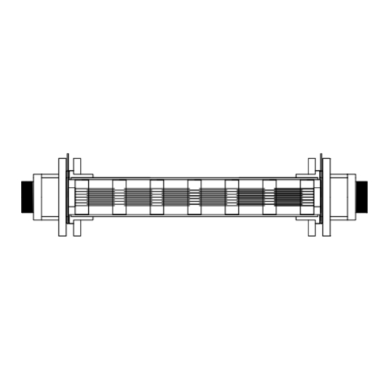
- Page 10 3.2.2- Célula de electrólisis PRO200V2 Se recomienda encarecidamente instalar un sistema de by-pass con el conjunto de células y llaves para cerrar el paso del agua, a la entrada y salida de cada célula. Conexión de las células al equipo: Una vez instaladas las células, conecte los cables, uno a cada extremo de la...
- Page 11 7-Brida 8-Inyector (colocar con la flecha hacia abajo) 9-Racor conversión 3/8,1/2 10-Brida 11-Entrada ácido (tubo aspiración) 12-Salida ácido (tubo inyección) 13-Conector sonda pH BCN 14-Líquido calibración pH4 15-Líquido calibración pH7 16-Tapón goma parar calibración 11 / 53 Manual PRO200V2 V2...
- Page 12 10- Colocar el porta-sonda (6) dentro de la brida (7). 11- Colocar la sonda de PH (5) dentro del porta-sonda (6). 12- Colocar el conector de la sonda de PH (5) en el conector BNC (13) del equipo. 12 / 53 Manual PRO200V2 V2...
- Page 13 Ofrece una baja dependencia del pH y de la concentración de ácido isocianúrico, así como la posibilidad de instalarse en piscinas de agua de mar (opción que debe solicitar previamente a BSV Electronic). Por favor, siga cuidadosamente las instrucciones de instalación, calibración y mantenimiento para asegurar un perfecto funcionamiento del kit.
- Page 14 Además, la instalación de este kit le permitirá utilizar el modo de control semi- automático. Puede obtener más detalles de este modo en el apartado 4.2 de este manual. 3.3- Esquema de conexionado eléctrico 3.3.1- Equipos PRO200V2 14 / 53 Manual PRO200V2 V2...
- Page 15 Para la configuración de la sonda de cloro libre se debe conectar a la regleta de entrada para sondas X4, tal y como se muestra en el apartado anterior. Para configurar los Jumpers de medida de cloro: ORP: Cloro libre: 15 / 53 Manual PRO200V2 V2...
- Page 16 El display mostrará el mensaje “paro” cuando esto ocurra. Esta entrada Filter solo consumirá unos pocos miliamperios. 16 / 53 Manual PRO200V2 V2...
-
Page 17: Operación
4- OPERACIÓN 4.1- Equipos PRO200V2 Los equipos PRO disponen de una pantalla LCD mediante el cual podrá visualizar y configurar todas las funciones del equipo. Menú Clorador: Menú configuración Lengua Menú principal Control Ciclo de limpieza de la célula Configuración Ácido (Alkali) - Page 18 (S) mediante la flecha y pulsando OK. 4.1.2.1- Menú Configuración El menú de configuración permite seleccionar parámetros de configuración que generalmente sólo hay que ajustar en el momento de la instalación del equipo. 18 / 53 Manual PRO200V2 V2...
- Page 19 Automático Seleccione este modo solamente si dispone de un Kit Advanced o PRO/2. Si no dispone de sonda, el equipo se comportará de manera aleatoria y acabará por detenerse y mostrar un error. 19 / 53 Manual PRO200V2 V2...
- Page 20 Nota: Para modificar esta configuración, se requiere introducir la contraseña “1234”. 4.1.2.1.5-Alarma pH El sistema de regulación de pH mostrará una alarma y parará la bomba de dosificación cuando dicha bomba permanezca en marcha durante más de 2 horas de forma ininterrumpida. 20 / 53 Manual PRO200V2 V2...
- Page 21 Ajustable: Permite indicar dentro de qué franja horaria permanecerá activado. Nota: En caso de producirse una alarma, el equipo detendrá su producción y mostrará la causa del problema por pantalla, independientemente de cómo haya configurado el aviso acústico. 21 / 53 Manual PRO200V2 V2...
- Page 22 Se realizará una súper cloración durante 24 horas. Si la filtración se desconecta, se suspende la súper cloración. 4.1.2.2.4.- Calibración sonda de cloro libre Si disponemos de sonda de cloro libre, aparece un menú que permite la calibración de la misma: 22 / 53 Manual PRO200V2 V2...
- Page 23 OK. Espere 60 segundos; el display indica el valor medido de pH7. Una vez transcurridos los 60 segundos, limpie la sonda y sumergala en la solución patrón de pH4 y pulse OK. Espere 60 segundos; el display indica el valor medido de pH4 23 / 53 Manual PRO200V2 V2...
- Page 24 Del mismo modo, mostrará una advertencia también en la 4ª línea, pero sin señal acústica ni detener el equipo. En este caso, el equipo puede seguir trabajando aunque le informa que debe tomar alguna acción correctiva. 24 / 53 Manual PRO200V2 V2...
- Page 25 No hay flujo de agua Revisar el sistema hidráulico “CORTOCIRCUITO” Mal conexionado de la célula. Verificar el cableado. Cuerpo metálico en la célula. Apagar el equipo y retirar el cuerpo metálico de las láminas 25 / 53 Manual PRO200V2 V2...
-
Page 26: Garantía Y Servicio
Desde la pantalla principal, pulse los dos botones a la vez. 5- GARANTÍA Y SERVICIO BSV Electronic S.L. garantiza sus equipos BSPOOL por un periodo de 3 años en sus centralitas de control. En las células de electrólisis, la garantía será de dos años siempre y cuando las mismas no hayan excedido las 12.000 horas de uso. - Page 27 En el caso de que falle el equipo se deberá devolver al fabricante o distribuidor. Los gastos de envío correrán a cargo del propietario del equipo. Debe tenerse en cuenta que todas las reparaciones en garantía se realizarán en fábrica. 27 / 53 Manual PRO200V2 V2...
- Page 28 INDEX 1- GENERAL DESCRIPTION 1.1- BSV PRO salt water chlorination equipment 1.2- Technical specifications 1.3- Recommendations and safety precautions 2- PREPARING THE SWIMMING POOL 2.1- Adding salt to the water 2.2 Chemical balance of the water 3- INSTALLATION OF THE EQUIPMENT 3.1- General considerations...
-
Page 29: General Description
Before installing the salt water chlorinator, please read this manual carefully. If you need to clarify any point or have any doubts, please contact your dealer or BSV ELECTRONIC S.L. directly. We will be delighted to assist you. 1- GENERAL DESCRIPTION 1.1- BSV PRO salt water chlorination equipment... - Page 30 Ensure that the heatsink wings are not blocked and that air can easily circulate through them. BSV PRO equipment incorporate protection systems against short circuits in the cell, absence of water detector and other safety systems that give an acoustic...
- Page 31 We also recommend not to add salt near the drain, to avoid undissolved salt from circulating in the water circuit. 31 / 53 Manual PRO200V2 V2...
- Page 32 <75 OZONE (GLASS) (mg/l) OZONE (before) TURBIDITY (NTU) <1 OXIDES (mg/l) <3 NITRATES (mg/l) <20 AMMONIA (mg/l) <0.3 IRON (mg/l) <0.3 COPPER (mg/l) <1.5 ALKALINITY (mg/l) CONDUCTIVITY (us/cm) <1700 TDS (mg/l) <1000 HARDNESS (mg/l) 32 / 53 Manual PRO200V2 V2...
-
Page 33: Installation Of The Equipment
A good earth connection is essential. Use a differential relay with max. 30mA of sensitivity. If a good quality earth connection is not available, place an earth connection kit between the electrolysis cell and the redox probe. OPTIONAL KIT 33 / 53 Manual PRO200V2 V2... - Page 34 3.2- Hydraulic connection diagram 3.2.1- PRO200V2 hydraulic diagram 1. From the swimming pool. 2. Filtration pump 3. Electrical Panel 4. Bypass 5. Flow Switch 6. Temperature probe (optional) 7. pH probe, included in AUTO kit (optional) 8. Redox probe, included in ADVANCED kit (optional) 9.
- Page 35 3.2.2- PRO200V2 Electrolysis Cell Diagram It is highly recommended to install a by-pass system, to be able to block the water flow in each cell for maintenance purposes. Connection of the cells to the equipment: Once the cells are installed, connect the cables, one at each end of the cell, using the screws that are included with the equipment.
- Page 36 9- Pipe nipple 3/8,1/2 10- Flange 11- Acid inlet (suction tube) 12- Acid outlet (injection tube) 13- pH probe connector (BNC) 14- pH4 calibration liquid 15- pH7 calibration liquid 16- Rubber cap for calibration 36 / 53 Manual PRO200V2 V2...
- Page 37 Connect the other end of the suction tube (2) to the suction filter (4). 5- Place the suction filter (4) inside the ACID drum. 6- Connect one end of the suction tube (3) to the PH control inlet (12). 37 / 53 Manual PRO200V2 V2...
- Page 38 This ppm measure has a low dependency of pH and isocyanuric acid, and it can be also installed in sea water swimming pools (this option to be asked to BSV Electronic). Please follow carefully the installation, calibration and maintenance instructions to ensure a perfect setup of the kit.
- Page 39 3.2.5.1- Electric connection to PRO200V2 Free chlorine probe must be direct to PRO200V2 input. Check the following figure. Furthermore, you must configure Jumper positions according to section 3.3.1 “ORP and Free Chlorine probe configuration”. Brown White Free Chlorine Probe 39 / 53...
- Page 40 ATTENTION: Please, remember CL probe must be connected to PRO200V2 directly. Its reading is galvanic isolated in the equipment. 3.2.5.2- Installation Please, follow the instructions form the specific PRO/2 kit manual. This manual details how to perform the following operations:...
-
Page 41: Electrical Connection Diagram
3.3- ELECTRICAL CONNECTION DIAGRAM 3.3.1- PRO200V2 units 1) Input connector X8: We recommend to set up wiring after filtration pump contactor. Connect 220VAC directly to monophasic line. 1- Ground(GND) 2- Live (L) 3- Neutral(N) 4- Main switch Live 5- Main switch Live 6- Filter Input 220VAC(L). - Page 42 Remove jumper from JP1, check figure 3.3 to find its location. Connect from filtration pump contactor output to filter input connector 220VAC cables. PRO200V2 will work with Start/Stop configuration. When filtration pump is on, Salt water chrlorinator will start production. PRO200V2 will stop when filtration pump switches off.
- Page 43 43 / 53 Manual PRO200V2 V2...
-
Page 44: Operation
4- OPERATION 4.1- PRO200V2 units The SMART series equipment has an LCD screen, in which you can view and configure all operations of the equipment. The following table shows how to organize the configuration menu of the equipment: Chlorinator Menu... - Page 45 To access the configuration menu, you need to confirm the operation by selecting (S) through the arrow, and pressing OK. 4.1.2.1- Configuration In the configuration menu you can select the configuration parameters, which usually only have to be adjusted when installing the equipment. 45 / 53 Manual PRO200V2 V2...
- Page 46 Select this mode if you do not have a Kit Advanced or PRO/2, by adjusting production and hours of filtering depending on the nature of your swimming pool, its volume number of bathers and season of the year. Automatic 46 / 53 Manual PRO200V2 V2...
- Page 47 Access this option from the "Configuration menu". To change this mode to another one, press OK and confirm the change of mode by selecting "S" and then press OK again. Note: Password “1234” is required to modify this function. 47 / 53 Manual PRO200V2 V2...
- Page 48 Note: In case of alarm, the unit will stop its production and will show the cause on the display, regardless of the acoustic alarm configuration. 4.1.2.2- Chorine menu With this menu you can select all parameters related to chlorine production. 48 / 53 Manual PRO200V2 V2...
- Page 49 Once the reading has stabilized and the chlorine measurement has been taken with DPD1, adjust the PPM value provided by the DPD1 measurement. 4.1.2.3- pH menu You can access the pH menu from the main menu by pressing OK 49 / 53 Manual PRO200V2 V2...
- Page 50 Go to the "pH" menu and select "Manual". Keeping the "OK" button pressed, the pump will be running. Keep the pump running with the "OK" button until the liquid has passed throughout the tube until injection. 4.2- Warning message and alarms 50 / 53 Manual PRO200V2 V2...
- Page 51 "NO WATER FLOW" Excess gas in the electrolysis The piping should be drained to cell. It may have occurred eliminate gas or accumulated water. because pump Check the pump. shutdown. hydrogen gas which is highly flammable. 51 / 53 Manual PRO200V2 V2...
-
Page 52: Warranty And Service
It may be useful to see the operation times for regular maintenance operations. From the main screen, press both buttons at the same time. 5- WARRANTY AND SERVICE BSV Electronic S.L. guarantees its BSPOOL equipment for a period of 3 years in control centres. 52 / 53... - Page 53 It is important to bear in mind that all repairs under guarantee are performed at the factory. BSV Electronic S.L. reserves the right to modify the equipment and the instructions manual without prior notice. Thank you for choosing the BSPOOL Salt Water Chlorinator for your swimming pool.
Need help?
Do you have a question about the PRO200V2 and is the answer not in the manual?
Questions and answers