Table of Contents
Advertisement
Quick Links
This user's guide describes the characteristics, operation, and use of the TMCS1100 evaluation module
(EVM). This EVM is designed to evaluate the performance of the
bidirectional Hall-effect current sense amplifiers in a variety of configurations. Throughout this document,
the terms evaluation board, evaluation module, and EVM are synonymous with the TMCS1100EVM. This
document includes a schematic, reference printed-circuit board (PCB) layouts, and a complete bill of
materials (BOM).
SBOU209A – August 2019 – Revised March 2020
Submit Documentation Feedback
Copyright © 2019–2020, Texas Instruments Incorporated
SBOU209A – August 2019 – Revised March 2020
TMCS1100EVM
TMCS1100
voltage output isolated
TMCS1100EVM
User's Guide
1
Advertisement
Table of Contents

Related Manuals for Texas Instruments TMCS1100


Summary of Contents for Texas Instruments TMCS1100
- Page 1 User's Guide SBOU209A – August 2019 – Revised March 2020 TMCS1100EVM This user’s guide describes the characteristics, operation, and use of the TMCS1100 evaluation module (EVM). This EVM is designed to evaluate the performance of the TMCS1100 voltage output isolated bidirectional Hall-effect current sense amplifiers in a variety of configurations.
-
Page 2: Table Of Contents
Contents ...... General Texas Instruments High Voltage Evaluation (TI HV EVM) User Safety Guidelines ........................Overview ......................Kit Contents .............. Related Documentation From Texas Instruments ........................Hardware ......................Features ......................Circuitry ........................Operation ...................... Measurements ..................Advanced Measurement Tips ................. -
Page 3: General Texas Instruments High Voltage Evaluation (Ti Hv Evm) User Safety Guidelines
Any other use and/or application are strictly prohibited by Texas Instruments. If you are not suitable qualified, you should immediately stop from further use of the HV EVM. -
Page 4: Overview
200 mV/A, and 400 mV/A. These devices operate from a single 3-V to 5.5-V power supply, drawing a maximum of 5 mA of supply current per amplifier channel. The TMCS1100 is currently available in an 8- pin, SOIC, surface-mount package. -
Page 5: Hardware
The TMCS1100 is an isolated, current-sense op amp that provides ease-of-use and high performance. The TMCS1100EVM is intended to provide basic functional evaluation of all TMCS1100 gain variants. The TMCS1100EVM is not laid out for electromagnetic compatibility (EMC) testing. The TMCS1100EVM consists of one PCB that can be snapped apart into four individual segments;... -
Page 6: Circuitry
TP3x serves as a test-point for the filtered input to the TMCS1100 VREF pin while TP7x serves as a test point for the prefiltered input to the TMCS1100 VREF pin. J1x is a jumper that conveniently allows the TMCS1100 reference to be shorted to ground, connected directly to an external power supply, or shorted to a voltage set by a buffered voltage divider. - Page 7 Reference Divider Buffer U3x is the TLV376IDBVR. U3X is configured as a buffer that sets the TMCS1100 at mid-supply according to the voltage divider composed of R3x and R4x by default. The user has the option to either short out this buffer with a 0-Ω...
-
Page 8: Operation
REF supply, remove the jumper short from J1x, and apply a supply to the VREF SOURCE and GND test points with a voltage set between GND and VCC. Step 5. Connect the input per Section 4.1. TMCS1100EVM SBOU209A – August 2019 – Revised March 2020 Submit Documentation Feedback Copyright © 2019–2020, Texas Instruments Incorporated... -
Page 9: Measurements
DUT package and placing a thermal sensor directly on the thermal grease. SBOU209A – August 2019 – Revised March 2020 TMCS1100EVM Submit Documentation Feedback Copyright © 2019–2020, Texas Instruments Incorporated... -
Page 10: Schematics, Pcb Layout, And Bill Of Materials
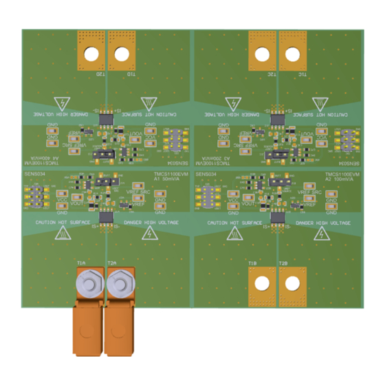
A1 (50 mV/A) gain variant is included as all variants use the same circuit and same PCB layout. All components associated with the 50-mV/A TMCS1100 A1 gain variant have the letter A appended at the end. The 100-mV/A A2 gain variant has B appended, the 200-mV/A A3 gain variant has C appended, and the 400-mV/A A4 gain variant has a D appended. -
Page 11: Pcb Layout
Schematics, PCB Layout, and Bill of Materials www.ti.com PCB Layout Figure 4 through Figure 7 illustrate the PCB layers of the TMCS1100EVM. Figure 4. Top Overlay SBOU209A – August 2019 – Revised March 2020 TMCS1100EVM Submit Documentation Feedback Copyright © 2019–2020, Texas Instruments Incorporated... -
Page 12: Top Layer
Schematics, PCB Layout, and Bill of Materials www.ti.com Figure 5. Top Layer TMCS1100EVM SBOU209A – August 2019 – Revised March 2020 Submit Documentation Feedback Copyright © 2019–2020, Texas Instruments Incorporated... -
Page 13: Bottom Overlay
Schematics, PCB Layout, and Bill of Materials www.ti.com Figure 6. Bottom Overlay SBOU209A – August 2019 – Revised March 2020 TMCS1100EVM Submit Documentation Feedback Copyright © 2019–2020, Texas Instruments Incorporated... -
Page 14: Bottom Layer
Schematics, PCB Layout, and Bill of Materials www.ti.com Figure 7. Bottom Layer TMCS1100EVM SBOU209A – August 2019 – Revised March 2020 Submit Documentation Feedback Copyright © 2019–2020, Texas Instruments Incorporated... -
Page 15: Bill Of Materials
Shunt, 100mil, Gold Shunt 2 pos. 100 mil 881545-2 TE Connectivity J1C, SH-J1D plated, Black T1A, T2A Terminal 50A Lug CB35-36-CY CB35-36-CY Panduit SBOU209A – August 2019 – Revised March 2020 TMCS1100EVM Submit Documentation Feedback Copyright © 2019–2020, Texas Instruments Incorporated... - Page 16 RES, 0, 1%, 0.1 W, AEC- 0603 RMCF0603ZT0R00 Stackpole Electronics Inc Q200 Grade 0, 0603 T1B, T1C, T1D, T2B, Terminal 50A Lug CB35-36-CY CB35-36-CY Panduit T2C, T2D TMCS1100EVM SBOU209A – August 2019 – Revised March 2020 Submit Documentation Feedback Copyright © 2019–2020, Texas Instruments Incorporated...
- Page 17 Changed step 4 in the Operation setup .................. • Changed the Advanced Measurement Tips section ....................• Changed the Bill of Materials table SBOU209A – August 2019 – Revised March 2020 Revision History Submit Documentation Feedback Copyright © 2019–2020, Texas Instruments Incorporated...
- Page 18 TI products. TI’s provision of these resources does not expand or otherwise alter TI’s applicable warranties or warranty disclaimers for TI products. Mailing Address: Texas Instruments, Post Office Box 655303, Dallas, Texas 75265 Copyright © 2020, Texas Instruments Incorporated...
Need help?
Do you have a question about the TMCS1100 and is the answer not in the manual?
Questions and answers