Advertisement
Quick Links
www.ti.com
EVM User's Guide: TMDSCNCD28P55X
TMDSCNCD28P55X controlCARD Information Guide
Description
The TMDSCNCD28P55X is a low-cost evaluation
and development board for TI C2000
series of F28P55x devices. The TMDSCNCD28P55X
comes with a HSEC180 (180-pin High speed edge
connector) and, as a controlCARD, is an excellent
choice for initial evaluation and prototyping. For
evaluation of TMDSCNCD28P55X, a 180-pin docking
station TMDSHSECDOCK is required and can be
purchased separately or as a bundled kit.
Features
•
F28P55X Microcontroller – High performance
C2000 microcontroller is located on the
controlCARD.
•
120-pin HSEC8 Edge Card Interface –
Allows for compatibility with all of C2000
180-pin controlCARD-based application kits
and controlCARDs. Compatibility with 100-pin
controlCARDs can be accomplished using the
TMDSADAP180TO100 adapter card.
•
Built-in Isolated JTAG Emulation – An XDS110
emulator provides a convenient interface to
SPRUJA7A – NOVEMBER 2023 – REVISED APRIL 2024
Submit Document Feedback
Code Composer Studio
hardware. Flipping a switch allows an external
JTAG emulator to be used.
™
MCU
•
Built-in Isolated Power Supply - Passes the
5V supply from the USB-C connector through an
isolation barrier. Allows for the controlCARD to be
completely powered and operated from the USB-C
connector. The F28P55X is fully isolated from the
USB port.
•
Automatic Power Supply Switch - The
controlCARD automatically switches to external 5V
power when present.
•
Connectivity – The controlCARD contains
connectors that allow the user to experiment with
isolated UART/SCI with the F28P55x MCU.
•
Key Signal Breakout – Most GPIO, analog-to-
digital converter (ADC) and other key signals
routed to hard gold connector fingers.
•
Robust Power Supply Filtering – Single 5V input
supply powers an on-card 3.3V LDO. All MCU
inputs are then decoupled using LC filters.
•
ADC Protection/Filtering – ADC inputs are
clamped by protection diodes and noise filters can
be easily added.
F28P55x controlCARD
Copyright © 2024 Texas Instruments Incorporated
™
IDE without additional
TMDSCNCD28P55X controlCARD Information Guide
Description
1
Advertisement

Related Manuals for Texas Instruments TMDSCNCD28P55X


Summary of Contents for Texas Instruments TMDSCNCD28P55X
- Page 1 Code Composer Studio ™ IDE without additional Description hardware. Flipping a switch allows an external The TMDSCNCD28P55X is a low-cost evaluation JTAG emulator to be used. and development board for TI C2000 ™ • Built-in Isolated Power Supply - Passes the series of F28P55x devices.
-
Page 2: Kit Contents
Evaluation Module Overview www.ti.com 1 Evaluation Module Overview 1.1 Introduction The F28P55x ControlCARD (TMDSCNCD28P55X) from Texas Instruments (TI) provides a great way to learn and experiment with the F28P55x devices. The F28P55x device is a member of TI’s C2000 ™ family of microcontrollers (MCUs). - Page 3 For additional information, refer to the TMS320F28P55x data sheet (SPRSP85). SPRUJA7A – NOVEMBER 2023 – REVISED APRIL 2024 TMDSCNCD28P55X controlCARD Information Guide Submit Document Feedback Copyright © 2024 Texas Instruments Incorporated...
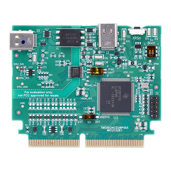
- Page 4 Figure 2-1. Key Components on the controlCARD - Front Emulation Circuitry – Isolated emulation circuitry Figure 2-2. Key Components on the controlCARD - Back TMDSCNCD28P55X controlCARD Information Guide SPRUJA7A – NOVEMBER 2023 – REVISED APRIL 2024 Submit Document Feedback Copyright © 2024 Texas Instruments Incorporated...
- Page 5 OFF – The C2000 MCU GPIO28 is NOT connected to the embedded XDS110. The corresponding pins on the 180-pin controlCARD connector can be used for another function. SPRUJA7A – NOVEMBER 2023 – REVISED APRIL 2024 TMDSCNCD28P55X controlCARD Information Guide Submit Document Feedback Copyright © 2024 Texas Instruments Incorporated...
- Page 6 0 (down, default) 1 (up, default) SCI / Wait Boot 1 (up) 0 (down) 1 (up) 1 (up) Flash / USB TMDSCNCD28P55X controlCARD Information Guide SPRUJA7A – NOVEMBER 2023 – REVISED APRIL 2024 Submit Document Feedback Copyright © 2024 Texas Instruments Incorporated...
- Page 7 3. LEDs D3, D5, D6 and D7 on the controlCARD illuminate. 2.2.2 Configuration 2: External 5V Supply 1. Insert the TMDSCNCD28P55X controlCARD into a TMDSHSECDOCK or other compatible docking station. 2. Connect a USB cable to J17 on the TMDSHSECDOCK.
- Page 8 5V power supply instability can lead to device resets. The 5V rail on the TMDSCNCD28P55X controlCARD can be powered from an on-board USB connector or from a baseboard like the TMDSHSECDOCK. A switch device on the controlCARD automatically selects the 5V input power source for the controlCARD without the need for user configuration.
- Page 9 30Ω resistors and 300pF capacitors were used. Using this setup, the ADC parameters were observed to be consistent with the numbers in the device-specific data sheet. Figure 2-3. Female SMA Connector SPRUJA7A – NOVEMBER 2023 – REVISED APRIL 2024 TMDSCNCD28P55X controlCARD Information Guide Submit Document Feedback Copyright © 2024 Texas Instruments Incorporated...
- Page 10 More information on the controlCARD docking station can be found in the C2000Ware at the following location: <install directory>\c2000\C2000Ware_<rev>\boards\controlCARDs\TMDSCNCD28P55X\Rx_x. TMDSCNCD28P55X controlCARD Information Guide SPRUJA7A – NOVEMBER 2023 – REVISED APRIL 2024 Submit Document Feedback Copyright © 2024 Texas Instruments Incorporated...
- Page 11 MCU and if the SCI (UART) pins on the MCU are connected to the COM port on the USB-C connector (see Table 3-1). Figure 3-1. XDS110 Emulation Circuitry and Isolation Circuitry SPRUJA7A – NOVEMBER 2023 – REVISED APRIL 2024 TMDSCNCD28P55X controlCARD Information Guide Submit Document Feedback Copyright © 2024 Texas Instruments Incorporated...
-
Page 12: Additional Information
4 Hardware Design Files 4.1 Schematics The controlCARD's schematic can be found at this link: TMDSCNCD28P55X-Schematic. 4.2 PCB Layouts The layout source files for the TMDSCNCD28P55X are included in the TMDSCNCD28P55X design files download. 4.3 Bill of Materials (BOM) The BOM for the TMDSCNCD28P55X is included in the TMDSCNCD28P55X design files download. - Page 13 STANDARD TERMS FOR EVALUATION MODULES Delivery: TI delivers TI evaluation boards, kits, or modules, including any accompanying demonstration software, components, and/or documentation which may be provided together or separately (collectively, an “EVM” or “EVMs”) to the User (“User”) in accordance with the terms set forth herein.
- Page 14 www.ti.com Regulatory Notices: 3.1 United States 3.1.1 Notice applicable to EVMs not FCC-Approved: FCC NOTICE: This kit is designed to allow product developers to evaluate electronic components, circuitry, or software associated with the kit to determine whether to incorporate such items in a finished product and software developers to write software applications for use with the end product.
- Page 15 www.ti.com Concernant les EVMs avec antennes détachables Conformément à la réglementation d'Industrie Canada, le présent émetteur radio peut fonctionner avec une antenne d'un type et d'un gain maximal (ou inférieur) approuvé pour l'émetteur par Industrie Canada. Dans le but de réduire les risques de brouillage radioélectrique à...
- Page 16 www.ti.com EVM Use Restrictions and Warnings: 4.1 EVMS ARE NOT FOR USE IN FUNCTIONAL SAFETY AND/OR SAFETY CRITICAL EVALUATIONS, INCLUDING BUT NOT LIMITED TO EVALUATIONS OF LIFE SUPPORT APPLICATIONS. 4.2 User must read and apply the user guide and other available documentation provided by TI regarding the EVM prior to handling or using the EVM, including without limitation any warning or restriction notices.
- Page 17 Notwithstanding the foregoing, any judgment may be enforced in any United States or foreign court, and TI may seek injunctive relief in any United States or foreign court. Mailing Address: Texas Instruments, Post Office Box 655303, Dallas, Texas 75265 Copyright © 2023, Texas Instruments Incorporated...
- Page 18 TI products. TI’s provision of these resources does not expand or otherwise alter TI’s applicable warranties or warranty disclaimers for TI products. TI objects to and rejects any additional or different terms you may have proposed. IMPORTANT NOTICE Mailing Address: Texas Instruments, Post Office Box 655303, Dallas, Texas 75265 Copyright © 2024, Texas Instruments Incorporated...
Need help?
Do you have a question about the TMDSCNCD28P55X and is the answer not in the manual?
Questions and answers