Lenze g500-B Manual
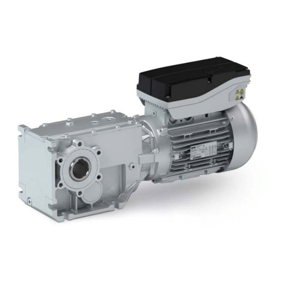
Mains-operated geared motors
Hide thumbs
Also See for g500-B:
- Manual (156 pages) ,
- Project planning manual (140 pages) ,
- Project planning (120 pages)

Related Manuals for Lenze g500-B


Summary of Contents for Lenze g500-B
- Page 1 Project planning EN Mains-operated geared motors Bevel geared motor g500-B / Smart Motor m300-E...
-
Page 3: Table Of Contents
Contents Contents About this document Document description Further documents Notations and conventions Product information Product description Identification of the products Features The modular system Information on project planning Safety instructions Basic safety instructions Application as directed Foreseeable misuse Residual hazards Drive dimensioning Final configuration Environmental conditions... - Page 4 Contents Product extensions Torque plates Shaft covers Motor connection Brakes Spring-applied brakes Brake resistors Accessories Overview NFC adapter QUICKON connector UMCLN_SGG_100181 Product codes Motor data Rated data Appendix Good to know Approvals/directives Operating modes of the motor Enclosures...
-
Page 5: About This Document
Please observe the notes in the following chapters! ▶ Safety instructions ^ 21 ▶ Information on mechanical installation ^ 36 ▶ Information on electrical installation ^ 37 Further documents Information and tools with regard to the Lenze products can be found on the Internet: http://www.lenze.com à Downloads... -
Page 6: Notations And Conventions
About this document Notations and conventions Notations and conventions This document uses the following conventions to distinguish different types of information: Numeric notation Decimal separator Point The decimal point is always used. Example: 1 234.56 Warning UL warning Are used in English and French. UR warning Text Engineering tools... -
Page 7: Product Information
This led to a large number of different drive variants.. Things are different with the Lenze Smart Products: Due to the possibility of freely adjusting the motor speed within a fivefold adjustment range at a constant torque, very different speeds can be enabled with one single drive variants. -
Page 8: Product Description
Only an NFC-capable Android smartphone or the Lenze NFC adapter for PCs is needed as a tool. The data can therefore be read and written when the drive is in a de-energised state –... - Page 9 Contactor and motor protection functions integrated The Lenze Smart Products can be started and stopped by mean of digital inputs. It is also possible to switch between different speeds and rotating directions. Up to 5 different speed modes (e.
-
Page 10: Identification Of The Products
Product information Identification of the products Application examples Roller conveyors with belt ejector Belt conveyors Identification of the products Gearbox product name Gearbox type Product series Type Rated torque Nm Product g500-B45 g500-B110 g500-B240 g500-B450 Bevel gearbox g500 g500-B600 g500-B820 1500 g500-B1500 2700... -
Page 11: Features
Product information Features Features Ventilation (depending on the mounting position) Oil filler plug (depending on the mounting position) Remove oil control plug (depending on the mounting position) Output shaft Oil drain plug (depending on the mounting position) Output flange Housing type Torque plate mounting Torque plate mounting Brake resistor connection... -
Page 12: The Modular System
Product information The modular system The modular system Values printed in bold are standard designs. Values that are not printed in bold are potential extensions, some of them including a surcharge. - Page 13 Product information The modular system Geared motors up to 450 Nm Gearboxes g500-B45 g500-B110 g500-B240 g500-B450 Min. motor assignment MSEMA□□ 063-42 063-42 063-42 063-42 Max. motor assignment MSEMA□□ 063-42 080-32 080-32 080-32 Technical data Max. output torque Min. drive torque 1.75 1.75 1.75...
- Page 14 Product information The modular system Geared motors from 600 Nm to 1500 Nm Gearboxes g500-B600 g500-B820 g500-B1500 Min. motor assignment MSEMA□□ 063-42 063-42 080-32 Max. motor assignment MSEMA□□ 080-32 080-32 080-32 Technical data Max. output torque 1500 Min. drive torque 1.75 1.75 Max.
- Page 15 Product information The modular system Models at the output NOTICE Please observe the available gearbox designs! Hollow shaft, with foot Without centring (HBR) With centring (HAR) Flange with through holes (HAK) Hollow shaft with shrink disc, with foot Without centring (SBR) With centring (SAR) Flange with through holes (SAK) Solid shaft, with foot...
- Page 16 Product information The modular system Models at the output Motor connection Cable gland Connectors External brake resistor Cooling: self-ventilated Without brake With brake With brake and manual release lever...
- Page 17 Product information The modular system Mounting positions Geared motors In the following graphics, the terminal box in position 2 is colour-coded. If the mounting position (A … F) changes, the terminal box positions (2 … 5) are rotated accordingly. To reduce the number of different versions, the gearboxes can also be ordered with combined mounting positions: g500-B45 in ABCDEF mounting position •...
- Page 18 Product information The modular system Terminal box The terminal box position (2 ... 5) must be given as a function of the mounting position. Solid shaft Please specify the shaft position 3 or 5 when ordering.
- Page 19 Product information The modular system Shrink disc Please specify the shrink disc position 3 or 5 when ordering. Flange and shrink disc are not possible in the same position. Flange Please specify the flange position 3 or 5 when ordering.
-
Page 20: Information On Project Planning
With the» Drive Solution Designer« you can carry out the drive dimensioning process quickly and with top quality. The software contains profound and proven expertise with regard to drive applications and mechatronic drive components. Please refer to your competent Lenze sales company. -
Page 21: Safety Instructions
Information on project planning Safety instructions Foreseeable misuse Safety instructions Disregarding the following basic safety measures and safety information may lead to severe personal injury and damage to property! Observe all specifications of the corresponding documentation supplied. This is the precondition for safe and trouble-free operation and for obtaining the product features specified. -
Page 22: Residual Hazards
Information on project planning Safety instructions Residual hazards Residual hazards Even if notes given are taken into consideration and protective measures are implemented, the occurrence of residual risks cannot be fully prevented. The user must take the residual hazards mentioned into consideration in the risk assessment for his/her machine/system. -
Page 23: Drive Dimensioning
Information on project planning Drive dimensioning Drive dimensioning Mains operation Check operating conditions Define required input variables Determine correction factor Determine product on the basis of the forces Calculated necessary output torque Calculate intensity Determine the product on the basis of the obtained data Final configuration Check operating conditions Check... - Page 24 Information on project planning Drive dimensioning Determine product on the basis of the forces Transmission element Gear wheels Sprockets Toothed belt pulleys Narrow V-belt ( depending on the ( depending on the preloading) preloading) ≥ 17 teeth = 1.0 ≥ 20 teeth = 1.0 With belt tightener= 2.0 - 1.5 - 2.0 Additional radial force factor f...
-
Page 25: Final Configuration
Output speed 2 [500/i ... 2600/i] rpm CW rotation: > 0 rpm Output speed 3 Lenze Smart motor with gearbox: The ratio i is Output speed 4 taken into account in the calculation of the output Output speed 5 speed. - Page 26 Information on project planning Final configuration Rotating direction of the output shaft The rotating direction of the output shaft is defined via the setpoint of the output speed. The rotating direction changes in case of a positive (n > 0) or negative (n < 0) speed. n <...
-
Page 27: Environmental Conditions
Information on project planning Final configuration Environmental conditions Environmental conditions Surface and corrosion protection (called OKS) Depending on the ambient conditions, the surface and corrosion protection system (called OKS) offers tailor-made solutions for optimum protection. Various surface coatings ensure that the motors operate reliably even at high air humidity, in outdoor installation or in the presence of atmospheric impurities. - Page 28 Information on project planning Final configuration Environmental conditions Lubricants In case of ambient temperatures < -20 °C or > +40 °C, please contact your responsible Lenze sales company The following gearboxes are lubricated for life: g500-B45 • g500-B110 • g500-B240 •...
-
Page 29: Free Spaces
Information on project planning Final configuration Free spaces Free spaces Ventilation For the gearboxes g500-B45 … B240, no ventilation measures are required. The gearbox g500-B240 can optionally be ordered with breather elements. From g500-B450 onwards, the gearboxes are generally outfitted with breather elements. - Page 30 Information on project planning Final configuration Free spaces g500-B240 Mounting position A Mounting position B Mounting position C Filling and ventilation Check Drain...
- Page 31 Information on project planning Final configuration Free spaces Mounting position D Mounting position E Mounting position F Filling and ventilation Check Drain...
- Page 32 Information on project planning Final configuration Free spaces g500-B450 Mounting position A Mounting position B Mounting position C Filling and ventilation Check Drain...
- Page 33 Information on project planning Final configuration Free spaces Mounting position D Mounting position E Mounting position F Filling and ventilation Check Drain...
- Page 34 Information on project planning Final configuration Free spaces g500-B600 ... B4300 Mounting position A Mounting position B Mounting position C Filling and ventilation ③ ① ④ ⑤ ② Check Drain g500-B600 ① g500-B820 ② g500-B1500 ③ g500-B2700 ④ g500-B4300 ⑤...
- Page 35 Information on project planning Final configuration Free spaces Mounting position D Mounting position E Mounting position F Filling and ventilation ④ ⑤ ① ③ ② ③ Check ③ Drain ① ② ④ ⑤ ③ g500-B600 ① g500-B820 ② g500-B1500 ③ g500-B2700 ④...
-
Page 36: Information On Mechanical Installation
4Environmental conditions ^ 27 Ambient media − especially chemically aggressive ones − may damage shaft sealing rings, • lacquers and plastics. If required, contact your responsible Lenze subsidiary. Transport Ensure appropriate handling. • Make sure that all component parts are safely mounted. Secure or remove loose •... -
Page 37: Information On Electrical Installation
Information on electrical installation Preparation Information on electrical installation Important notes DANGER! Hazardous voltage! On the power connections even when disconnected from the mains: residual voltage >60 V! ▶ Disconnect the product from the mains and wait until the motor is at a standstill. ▶... -
Page 38: Connection According To En
Information on electrical installation Connection according to EN Connection according to EN The following data is valid for a three-phase mains connection with 400 V. Mains connection with QUICKON connector Motor MSEMA☐☐063-42 MSEMA☐☐080-32 Connection Laying system Connection type QUICKON connector Cable type Flexible Cable cross-section... - Page 39 Information on electrical installation Connection according to EN Single drive connection according to EN 60204-1 3/N/PE AC 400/480 V SELV/PELV F1 … F3 F1 … F3 DC 24 V (+19.2 … +28.8 V) max. 50 mA n. c. L2 L3 Rb1 Rb2 L2 L3 Rb1 Rb2...
- Page 40 Information on electrical installation Connection according to EN Connection for group drive according to EN 60204-1 F1 … F3 PE L1 L2 L3 PE L1 L2 L3 PE L1 L2 L3 PE L1 L2 L3 PE L1 L2 L3 Max. total rated mains currents at 40 °C Cable installation in accordance EN 60204-1 with...
-
Page 41: Connection According To Ul
Information on electrical installation Connection according to UL Connection according to UL The following data is valid for a three-phase mains connection with 480 V. Mains connection with QUICKON connector Motor MSEMA☐☐063-42 MSEMA☐☐080-32 Connection Connection type QUICKON connector Cable cross-section Typ. - Page 42 Information on electrical installation Connection according to UL General UL notes WARNING! ▶ UL marking ▶ Use 75 °C copper wire only, except for control circuits. ▶ Maximum conductor size is AWG14. ▶ Cord connected drives are for use only in NFPA 79 applications. ▶...
- Page 43 Information on electrical installation Connection according to UL Fuse data (F1 ... F3) Motor MSEMA☐☐063-42 MSEMA☐☐080-32 Cable installation in compliance UL 61800-5-1 with Fuse Standard UL 248 Typ. rated current Max. rated current Semiconductor fuse Standard UL 248 Typ. rated current Max.
- Page 44 Information on electrical installation Connection according to UL Max. total rated mains currents at 40 °C Cable installation in accordance UL 61800-5-1 with Main cable Cable cross-section Stub Cable cross-section Fuse Typ. rated current Max. rated current Circuit breaker Typ. rated current Max.
-
Page 45: Technical Data
The ratings apply to the operating mode S1 (acc. to EN 60034). • NOTICE In case of other operating conditions, the achievable values can differ for those mentioned. ▶ In case of extreme operating conditions, please contact your responsible Lenze sales company. -
Page 46: Standards And Operating Conditions
Approval GB Standard 12350-2009 cULus UL 61800-5-1 for USA and Canada (requirements of the CSA 22.2 No. 14) Industrial Control Equipment, Lenze File No. E132659 Protection of persons and device protection Degree of protection IP55 EN 60529 Type 4 indoor only... -
Page 47: Emc Data
Technical data Standards and operating conditions Electrical supply conditions EMC data Actuation on public supply systems Implement measures to limit the radio The machine or plant manufacturer is responsible for compliance interference to be expected: with the requirements for the machine/plant! <... -
Page 48: Radial Forces And Axial Forces
Technical data Radial forces and axial forces Radial forces and axial forces Permissible radial force The calculation of the permissible radial force must take account of the additional load factor rad, perm rad,max Permissible axial force If there is no radial force, the maximum axial force is 50% of the value in the table F rad,max = 0.5 x F ax, zul... - Page 49 The values were calculated with a load capacity of c= 1.3 and an input speed of 1400 rpm. In case of different operating conditions, considerably higher forces can be transmitted. Please contact Lenze. A hollow shaft with shrink disc (SAR/SBR/SCR/SDR/SAK/SCK) requires a check by Lenze.
-
Page 50: Selection Tables
Technical data Selection tables Selection tables Notes on the selection tables The selection tables represent the available combinations of gearbox, number of stages, ratio and motor for the mounting position A. They only serve as a rough overview. The following legend shows the layout of the selection tables: Example Explanation = 7.0 Nm... - Page 51 Technical data Selection tables = 7 Nm Max. Mains operation Geared motor Number of stages Min. output speed Max. output speed Starting torque g500- MSEMA☐☐ a, 1 a, 2 kgcm² 5.185 B110 063-42 5.411 063-42 5.963 B110 063-42 6.222 063-42 7.111 063-42 7.111 B110 063-42...
- Page 52 Technical data Selection tables Mains operation Geared motor Number of stages Min. output speed Max. output speed Starting torque g500- MSEMA☐☐ a, 1 a, 2 kgcm² 49.133 B240 063-42 50.167 B450 063-42 52.510 B240 063-42 56.154 B450 063-42 59.630 B240 063-42 61.045 B110...
- Page 53 Technical data Selection tables = 20 Nm Max. Mains operation Geared motor Number of stages Min. output speed Max. output speed Starting torque g500- MSEMA☐☐ a, 1 a, 2 kgcm² 3.565 B240 080-32 5.002 B450 080-32 5.185 B110 080-32 5.963 B110 080-32 6.257 B240 080-32...
- Page 54 Technical data Selection tables Mains operation Geared motor Number of stages Min. output speed Max. output speed Starting torque g500- MSEMA☐☐ a, 1 a, 2 kgcm² 49.133 B240 080-32 50.167 B450 080-32 52.510 B240 080-32 56.154 B450 080-32 1025 57.662 B820 080-32 62.262...
-
Page 55: Dimensions
If the mounting area (foot support) towards the motor is longer than the gearbox foot, some motors collide with the mounting area! For an accurate check of the geometrical data, Lenze recommends the use of the »Product Finder« at www.Lenze.com. - Page 56 Technical data Dimensions Basic dimensions g500-B45 Gearbox design: hollow shaft, with foot (HAR/HBR/HAK) Motor MSEMA☐☐ 063-42 Total length Motor length Length of motor options Δ L Motor diameter Motor/connection distance...
- Page 57 Technical data Dimensions Basic dimensions g500-B45 Gearbox design: hollow shaft with shrink disc, with foot (SAR/SBR/SAK) Motor MSEMA☐☐ 063-42 Total length Motor length Length of motor options Δ L Motor diameter Motor/connection distance...
- Page 58 Technical data Dimensions Basic dimensions g500-B45 Gearbox design: solid shaft, with foot (VAR/VBR/VAK) Motor MSEMA☐☐ 063-42 Total length Motor length Length of motor options Δ L Motor diameter Motor/connection distance...
- Page 59 Technical data Dimensions Basic dimensions g500-B110 Gearbox design: hollow shaft, with foot (HAR/HBR/HAK) Motor MSEMA☐☐ 063-42 080-32 Total length Motor length Length of motor options Δ L Motor diameter Motor/connection distance...
- Page 60 Technical data Dimensions Basic dimensions g500-B110 Gearbox design: hollow shaft with shrink disc, with foot (SAR/SBR/SAK) Motor MSEMA☐☐ 063-42 080-32 Total length Motor length Length of motor options Δ L Motor diameter Motor/connection distance...
- Page 61 Technical data Dimensions Basic dimensions g500-B110 Gearbox design: solid shaft, with foot (VAR/VBR/VAK) Motor MSEMA☐☐ 063-42 080-32 Total length Motor length Length of motor options Δ L Motor diameter Motor/connection distance...
- Page 62 Technical data Dimensions Basic dimensions g500-B240 Gearbox design: hollow shaft, with foot (HAR/HBR/HAK) Motor MSEMA☐☐ 063-42 080-32 Total length Motor length Length of motor options Δ L Motor diameter Motor/connection distance...
- Page 63 Technical data Dimensions Basic dimensions g500-B240 Gearbox design: hollow shaft with shrink disc, with foot (SAR/SBR/SAK) Motor MSEMA☐☐ 063-42 080-32 Total length Motor length Length of motor options Δ L Motor diameter Motor/connection distance...
- Page 64 Technical data Dimensions Basic dimensions g500-B240 Gearbox design: solid shaft, with foot (VAR/VBR/VAK) Motor MSEMA☐☐ 063-42 080-32 Total length Motor length Length of motor options Δ L Motor diameter Motor/connection distance...
- Page 65 Technical data Dimensions Basic dimensions g500-B450 Gearbox design: hollow shaft, with foot (HAR/HBR/HAK) Motor MSEMA☐☐ 063-42 080-32 Total length Motor length Length of motor options Δ L Motor diameter Motor/connection distance...
- Page 66 Technical data Dimensions Basic dimensions g500-B450 Gearbox design: hollow shaft with shrink disc, with foot (SAR/SBR/SAK) Motor MSEMA☐☐ 063-42 080-32 Total length Motor length Length of motor options Δ L Motor diameter Motor/connection distance...
- Page 67 Technical data Dimensions Basic dimensions g500-B450 Gearbox design: solid shaft, with foot (VAR/VBR/VAK) Motor MSEMA☐☐ 063-42 080-32 Total length Motor length Length of motor options Δ L Motor diameter Motor/connection distance...
- Page 68 Technical data Dimensions Basic dimensions g500-B600 Gearbox design: hollow shaft, with foot (HAR/HBR/HAK) Motor MSEMA☐☐ 063-42 080-32 Total length Motor length Length of motor options Δ L Motor diameter Motor/connection distance...
- Page 69 Technical data Dimensions Basic dimensions g500-B600 Gearbox design: hollow shaft with shrink disc, with foot (SAR/SBR/SAK) Motor MSEMA☐☐ 063-42 080-32 Total length Motor length Length of motor options Δ L Motor diameter Motor/connection distance...
- Page 70 Technical data Dimensions Basic dimensions g500-B600 Gearbox design: solid shaft, with foot (VAR/VBR/VAK) Motor MSEMA☐☐ 063-42 080-32 Total length Motor length Length of motor options Δ L Motor diameter Motor/connection distance...
- Page 71 Technical data Dimensions Basic dimensions g500-B820 Gearbox design: hollow shaft, with foot (HAR/HBR/HAK) Motor MSEMA☐☐ 063-42 080-32 Total length Motor length Length of motor options Δ L Motor diameter Motor/connection distance...
- Page 72 Technical data Dimensions Basic dimensions g500-B820 Gearbox design: hollow shaft with shrink disc, with foot (SAR/SBR/SAK) Motor MSEMA☐☐ 063-42 080-32 Total length Motor length Length of motor options Δ L Motor diameter Motor/connection distance...
- Page 73 Technical data Dimensions Basic dimensions g500-B820 Gearbox design: solid shaft, with foot (VAR/VBR/VAK) Motor MSEMA☐☐ 063-42 080-32 Total length Motor length Length of motor options Δ L Motor diameter Motor/connection distance...
- Page 74 Technical data Dimensions Basic dimensions g500-B1500 Gearbox design: hollow shaft, with foot (HAR/HBR/HAK) Motor MSEMA☐☐ 080-32 Total length Motor length Length of motor options Δ L Motor diameter Motor/connection distance...
- Page 75 Technical data Dimensions Basic dimensions g500-B1500 Gearbox design: hollow shaft with shrink disc, with foot (SAR/SBR/SAK) Motor MSEMA☐☐ 080-32 Total length Motor length Length of motor options Δ L Motor diameter Motor/connection distance...
- Page 76 Technical data Dimensions Basic dimensions g500-B1500 Gearbox design: solid shaft, with foot (VAR/VBR/VAK) Motor MSEMA☐☐ 080-32 Total length Motor length Length of motor options Δ L Motor diameter Motor/connection distance...
-
Page 77: Weights
Technical data Weights Additional weights Weights Basic weights Weights with oil filling for mounting position A, all values are approximate weights must be observed! 4Additional ^ 77 2-stage gearbox Geared motor MSEMAXX063-42 MSEMAXX080-32 g500-B45 g500-B110 10,6 17,2 g500-B240 14,9 21,5 3-stage gearbox Geared motor MSEMAXX063-42... -
Page 78: Product Extensions
Product extensions Product extensions Torque plates The torque support is usually effected by means of the foot or flange. The torque plates that can be fitted are another possibility. In this case, the torque support is provided only via one point and is suitable for shaft-mounted gearboxes, among other things. - Page 79 Product extensions Torque plates Torque plate on threaded pitch circle g500-B45 ...B110 Gearbox Dimensions Mass g500-B45 12.0 20.0 42.0 g500-B110 13.0 10.0 25.0 54.0 11.0...
- Page 80 Product extensions Torque plates g500-B820 ... B1500 Gearbox Dimensions Mass g500-B820 38.0 28.0 31.5 40.0 20.0 50.0 20.5 g500-B1500 44.0 32.0 36.0 46.0 25.0 65.0 24.0...
- Page 81 Product extensions Torque plates Torque plate at housing foot g500-B240 g500-B450 Gearbox Mass g500-B240 g500-B450...
- Page 82 Product extensions Torque plates g500-B600 ... B4300 Gearbox Dimensions Mass g500-B600 16.4 40.0 55.0 60.0 18.0 g500-B820 16.4 45.0 55.0 60.0 25.0 g500-B1500 16.4 52.5 55.0 60.0 25.0 g500-B2700 25.0 60.0 72.0 80.0 30.0 10.0 g500-B4300 25.0 70.0 92.0 40.0 13.0...
- Page 83 Product extensions Torque plates Rubber buffer for torque plate g500-B45...
-
Page 84: Shaft Covers
Product extensions Shaft covers Shaft covers The hoseproof hollow shaft cover protects the hollow shaft from objects falling in. It is sealed by a flat gasket between cover and housing. Thus, the hollow shaft is protected from dust and water jets. The cover is loosely enclosed and can be mounted on both sides of the hollow shaft bore. - Page 85 Product extensions Shaft covers Hoseproof hollow shaft cover g500-B45 ..B4300 Product Dimensions Mass g500-B45 55.0 g500-B110 65.0 g500-B240 75.0 g500-B450 79.5 g500-B600 90.0 g500-B820 97.0 g500-B1500 g500-B2700 g500-B4300...
- Page 86 Product extensions Shaft covers Shrink disc cover g500-B45 ... B4300 Product Dimensions Mass g500-B45 65.0 87.5 g500-B110 79.0 97.5 g500-B240 90.0 g500-B450 90.0 g500-B600 g500-B820 g500-B1500 g500-B2700 g500-B4300...
-
Page 87: Motor Connection
Product extensions Motor connection Motor connection The QUICKON connection enables fast and easy connection of motors. The equipment is easy to cable by means of a connecting cable with the QUICKON nut. QUICKON nuts and QUICKON connectors with QUICKON nuts are available as accessories. - Page 88 Product extensions Motor connection Control terminal X2 Pin assignment for M12 connector A coded, pins Contac Name Meaning 24 V-supply (DO1 supply) Digital input 3 (reference X1;3 = GND-I) GND-O Mass of digital output Digital output 1...
-
Page 89: Brakes
Product extensions Brakes Spring-applied brakes Brakes Spring-applied brakes Motors with brake are equipped with a spring-applied brake. It becomes active when the supply voltage is switched off (closed-circuit principle). Features Designs Standard 1 x 10 switching cycles, repeating 1 x 10 switching cycles, repeating LongLife 10 x 10... - Page 90 Product extensions Brakes Spring-applied brakes Rated data with standard braking torque Motor MSEMABR063-42 MSEMABR080-32 Brake size Power input 0.020 0.025 Braking torque at output speed 100 rpm 4.00 8.00 1000 rpm 3.70 7.20 1200 rpm 3.60 7.00 1500 rpm 3.50 6.80 1800 rpm 3.40...
-
Page 91: Brake Resistors
Brake resistors Brake resistors The Lenze Smart Motor can be braked in a guided manner along a ramp. If large amounts of regenerative energy are produced during braking, they must be absorbed by a brake resistor. In addition to a brake resistor (10 W) mounted inside the terminal box, another brake resistor (20 W) can also be connected externally alongside the terminal box via the terminal X4. -
Page 92: Accessories
M15 connector NFC adapter The settings of the Lenze Smart Products can be made with an NFC-capable Android smartphone or a PC. If a PC is used to make the settings, the »EASY Starter« engineering tool must be used to do this (»EASY Advanced« software licence). Communication takes place via the NFC adapter. -
Page 93: Quickon Connector
Accessories UMCLN_SGG_100181 QUICKON connector Nuts for QUICKON connection For fast and easy QUICKON connection, the following nuts (counterparts) can be fitted to the connecting cable. No special tools are needed for installation, only standard tools for stripping the cable. NOTICE In the case of the capability for frequent connections (>10 times) a QUICKON connector with nut must be used. -
Page 94: Product Codes
Product codes Product codes Gearbox product code Example Product type Gearboxes Product family Generation Gearbox type Bevel gearbox Output torque 45 Nm 110 Nm 240 Nm 450 Nm 600 Nm 820 Nm 1500 Nm 2700 Nm 4300 Nm 8000 Nm 13000 Nm 20000 Nm Type of construction... - Page 95 Product codes Motor product code Example Meaning Variant Product code Product family Motor Product type Smart Motor Cooling Integral fan Internal key Built-on accessories Without built-on accessories Brake Size Overall length Number of pole pairs 4-pole motors Design types Internal key Approval CE;...
-
Page 96: Motor Data
Motor data Rated data Motor data Rated data Motor MSEMA☐☐063-42 MSEMA☐☐080-32 Mains voltage 3 400 ... 480 AC 3 400 ... 480 AC 1.75 Rated torque 20.0 Starting torque -2600 ... -500 / 0 / 500 ... 2600 Adjustment range Rated current 400 V 480 V... -
Page 97: Appendix
Appendix Approvals/directives Appendix Good to know Approvals/directives China Compulsory Certification documents the compliance with the legal product safety requirements of the PR of China - in accordance with Guobiao standards. CSA certificate, tested according to US and Canada standards Union Européenne documents the declaration of the manufacturer that EU Directives are complied with. -
Page 98: Operating Modes Of The Motor
Appendix Good to know Operating modes of the motor Operating modes of the motor Operating modes S1 ... S10 as specified by EN 60034-1 describe the basic stress of an electrical machine. In continuous operation a motor reaches its permissible temperature limit if it outputs the rated power dimensioned for continuous operation. -
Page 99: Enclosures
Appendix Good to know Enclosures Enclosures The degree of protection indicates the suitability of a motor for specific ambient conditions with regard to humidity as well as the protection against contact and the ingress of foreign particles. The degrees of protection are classified by EN 60529. The first code number after the code letters IP indicates the protection against the ingress of foreign particles and dust. - Page 100 © 05/2019 | | 1.0 Ö Lenze Drives GmbH Postfach 10 13 52, D-31763 Hameln Breslauer Straße 3, D-32699 Extertal Germany HR Lemgo B 6478 +49 5154 82-0 Ü Ø +49 5154 82-2800 sales.de@lenze.com Ù www.lenze.com Ú...
Need help?
Do you have a question about the g500-B and is the answer not in the manual?
Questions and answers