
Related Manuals for ETC SolarFrame 750


Summary of Contents for ETC SolarFrame 750
- Page 1 High End Systems SolaFrame 750 Automated Luminaire User Manual Version 1.2.11 Part Number: 2560M1200-1.2.11 Rev: A Released: 2021-06...
- Page 2 To view a list of ETC trademarks and patents, go to etcconnect.com/ip. All other trademarks, both marked and not marked, are the property of their respective owners. You can find complete High End Systems terms and conditions and warranty information at etcconnect.com/Support/Warranty.aspx.
-
Page 3: Table Of Contents
Table of Contents Introduction Important Safety Information Help from Technical Services Safety Considerations General Operation and Use Guidelines Fixture Overview Install the Fixture Power Electrical Specifications Input and Power Factor Connector Specification DMX Control DMX Connector Pinout Connect DMX Cables to Fixture DMX Control and Ethernet Output Terminate DMX Set the DMX Start Address... - Page 4 Ethernet Control and DMX Thru Terminate DMX Set the DMX Start Address Set the Control Input and Universe Configure the Fixture Navigate the User Interface Set Fixture Parameters DMX Address Info Menu Set Menu Test Menu Preset Menu Error Codes Maintenance Clean the Fixture Replace the Fuse...
-
Page 5: Introduction
RISK OF ELECTRIC SHOCK! This warning statement indicates situations where there is a risk of electric shock. All ETC High End Systems documents are available for free download from our website: etcconnect.com/Products/Live-Events. Please email comments about this manual to: TechComm@etcconnect.com. -
Page 6: Help From Technical Services
Help from Technical Services If you are having difficulties and your problem is not addressed by this document, try the ETC support website at support.etcconnect.com or the High End Systems product website at etcconnect.com/Products/Live-Events. If none of these resources are sufficient, contact ETC Technical Services directly at one of the offices identified below. -
Page 7: Safety Considerations
The SolaFrame 750 is intended for professional use only. Not for residential use. Read the • entire manual before using this equipment. Contact your ETC authorized dealer or Technical Services before performing any service in • order to maintain warranty coverage. - Page 8 Surfaces chaudes. Laissez le luminaire refroidir complètement avant de le manipuler et de procéder à son entretien. Note: The light source in this luminaire is not user-replaceable, and must be replaced only by a qualified technician. Contact ETC Customer Support for assistance. SolaFrame 750 User Manual...
-
Page 9: General Operation And Use Guidelines
Applying power to a cold fixture may cause damage to the fixture and void the manufacturer warranty. Please use the original packaging if the fixture is to be transported. ETC will not be •... -
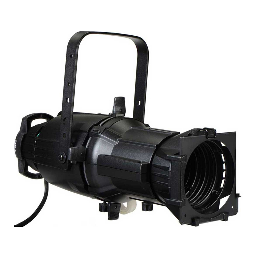
Page 10: Fixture Overview
Fixture Overview For technical specifications of the SolaFrame 750 fixture, see the technical datasheet: etcconnect.com/Products/High-End-Systems/Lighting-Fixtures/SolaFrame/750/Documentation.aspx 1. Lens 2. Tilt lock 3. Pan lock 4. Display 5. Navigation controls 6. Enclosure handle 7. Fuse 8. Power In and Power Out 9. DMX In and DMX Out 10. -
Page 11: Install The Fixture
Install the Fixture WARNING: NEMA Type 1 enclosure, indoor use, dry locations only. Do not use • outdoors. This fixture is intended for use where humidity does not exceed 90% (non-condensing). The operating temperature range for this fixture is 0°C–45°C (32°F– •... - Page 12 CAUTION: Follow all local codes and recommended practices by the Authority Having Jurisdiction. The installation must only be carried out by qualified personnel. ATTENTION : Respectez tous les règlements locaux et toutes les pratiques recommandées par l'autorité compétente. L'installation doit être effectuée uniquement par du personnel qualifié.
- Page 13 1. Assemble the clamp (provided by others) to the Omega bracket that was provided with the fixture and secure together using appropriately sized hardware (not provided). 2. Align the assembled Omega bracket and quick-lock fasteners into the respective holes on the bottom of the fixture upper enclosure.
-
Page 14: Power
Power Electrical Specifications 100–240 VAC at 50/60 Hz • Maximum power consumption: Standard mode 515 W; with Defogger 562 W • Input and Power Factor The values listed below were measured with LEDs at full and all motors functioning. Amps Watts 5.62 0.578... -
Page 15: Dmx Control
DMX Control The SolaFrame 750 fixture operates on standard DMX-512 control bus, controlled by a DMX console. The fixture requires 47 channels of DMX-512. Attach the fixture to the control bus using a two-core, shielded cable with a 5-pin XLR connector (Belden 9729 is preferred). -
Page 16: Connect Dmx Cables To Fixture
A DMX terminator is an XLR plug with a 120 Ω resistor connected between pins 2 and 3 that can be installed into the DMX output receptacle of the last fixture in the DMX control run. This plug is available and sold separately. Contact your authorized dealer or ETC for ordering information (etcconnect.com/contactETC/). -
Page 17: Set The Dmx Start Address
1, you could set the second fixture to 48 (47+1), the third to 95 (48+47), and so on. DMX Channels The current DMX channel map for the SolaFrame 750 can be found on the ETC website: etcconnect.com/Products/High-End-Systems/Lighting-Fixtures/SolaFrame/750/Documentation.aspx Ethernet Control The SolaFrame 750 fixture includes two Ethernet ports that allow sending and receiving of control signals using the Art-Net protocol or sACN. -
Page 18: Ethernet Control And Dmx Thru
A DMX terminator is an XLR plug with a 120 Ω resistor connected between pins 2 and 3 that can be installed into the DMX output receptacle of the last fixture in the DMX control run. This plug is available and sold separately. Contact your authorized dealer or ETC for ordering information (etcconnect.com/contactETC/). -
Page 19: Configure The Fixture
Configure the Fixture You can configure SolaFrame 750 fixtures through the onboard user interface. Navigate the User Interface 1. Press and hold the [MODE/ESC] button until the display flashes. (The display is powered by battery when the fixture has no power.) 2. -
Page 20: Set Fixture Parameters
Set Fixture Parameters This section provides instructions to configure and set up the SolaFrame 750. See Navigate the User Interface on page 15 for information about the navigation buttons. Provide power to the fixture before configuring it. If you do not provide power, the fixture will use battery power to power the user interface. - Page 21 View the DMX value of each of the fixture's channels (parameters of the fixture). Scroll to the parameter that you want to view (Pan, Tilt, etc.) and view the value. The DMX value that you view is the DMX value that displays on the main window of the UI until you select a different DMX value to view.
-
Page 22: Set Menu
Set Menu Set the Status Options Navigate: Main Menu → Set → Status Parameter Value Description Close • Control mode when DMX is absent. The default value No DMX Mode Hold • is Hold. Auto • Reverse the pan movement of the fixture. The default •... - Page 23 Select Input Navigate: Main Menu → Set → Select Input Select the control input for the fixture: DMX Only • Art-Net on IP2 • Art-Net on IP10 • sACN • Set Universe for Art-Net and sACN Navigate: Main Menu → Set → Set Universe When using Art-Net control input, set a universe value of 000–255.
- Page 24 Set the Fans Mode Navigate: Main Menu → Set → Fans Mode Setting Select the fan mode for the fixture: Standard • Studio (reduces fan noise, but decreases fixture output by ~20%) • Continuous • Set Display Settings Navigate: Main Menu → Set → Disp. Setting Parameter Value Description...
-
Page 25: Test Menu
Test Menu Reset (Home) the Mechanical Positions on the Fixture Navigate: Main Menu → Test → Home Reset ("home") all features on the fixture, including, pan, tilt, colors, gobos, etc. Test the Fixture Navigate: Main Menu → Test → Self Test Run a self-test program on the fixture. When you run the test, the display indicates "Running"... -
Page 26: Error Codes
Error Codes When you apply power to the fixture, it runs a calibration (homing) sequence and displays any errors that it detects. Example: When the display shows “Err Info: Pan Movement”, it means there is an error in channel 1. When multiple errors are present they will cycle on the display twice, and then the fixture will reset (restart). - Page 27 Gobo 1 This message displays after the reset of the fixture if any of the following conditions exist: the magnetic-indexing circuit malfunctions (optical or magnetic sensor failure) • the stepper motor is defective or the related IC driver on the main PCB has failed •...
-
Page 28: Maintenance
Maintenance CAUTION: RISK OF ELECTRIC SHOCK! Disconnect power before servicing. ATTENTION : RISQUE DE CHOC ÉLECTRIQUE! Couper l'alimentation avant l'entretien. Keep the following in mind during regular service and inspection: All screws for installing the fixture or parts of the fixture must be tightly connected and •... -
Page 29: Compliance
4. Reinstall the fuse holder. Using a flatblade screwdriver, push the holder in and twist it until it is secure in the fixture. Compliance For current and complete compliance information, view the SolaFrame 750 datasheet: etcconnect.com/Products/High-End-Systems/Lighting-Fixtures/SolaFrame/750/Documentation.aspx FCC Compliance SolaFrame 750 (For any FCC matters): Electronic Theatre Controls, Inc. -
Page 30: Declarations Of Conformity
Declarations of Conformity EC DECLARATION OF CONFORMITY We, Electronic Theatre Controls France SAS declare under sole responsibility that the product(s): Product series: High End Systems Sola LED luminaire Product type/model: SolaFrame 750 to which this declara on relates is/are in conformity with the following Direc ves by the applica on of the quoted Standards. - Page 31 UK DECLARATION OF CONFORMITY We, Electronic Theatre Controls Limited declare under sole responsibility that the product(s): Product series: High End Systems Sola LED luminaire Product type/model: SolaFrame 750 to which this declara on relates is/are in conformity with the following Direc ves by the applica on of the quoted Standards.
- Page 32 | Support support.etcconnect.com | Contact etcconnect.com/contactETC © 2021 Electronic Theatre Controls, Inc. | Trademark and patent info: etcconnect.com/ip Product information and specifications subject to change. ETC intends this document to be provided in its entirety. 2560M1200-1.2.11 Rev A Released 2021-06...
Need help?
Do you have a question about the SolarFrame 750 and is the answer not in the manual?
Questions and answers