Table of Contents
Advertisement
Quick Links
®
This publication contains the installation, operation and
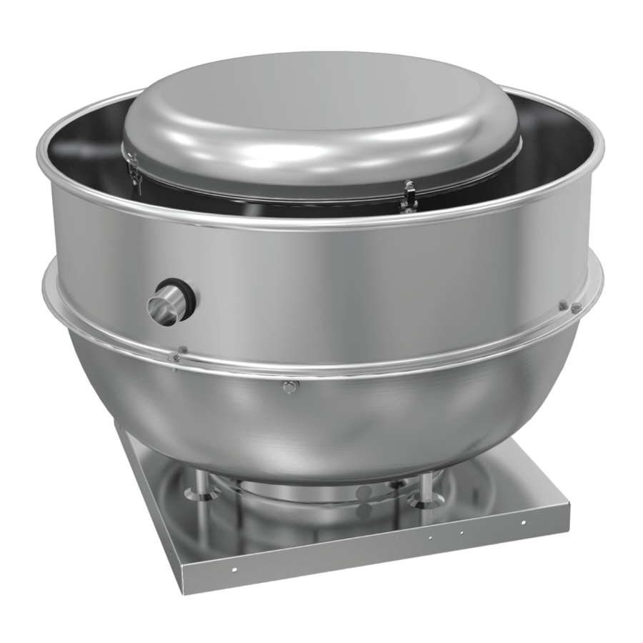
maintenance instructions for standard units of the Lo-Pro:
Low Profile Centrifugal Exhaust Fans (LPD & LPB).
Carefully read this publication and any
supplemental documents prior to any
installation or maintenance procedure.
Loren Cook catalog, Lo-Pro, provides additional information
describing the equipment, fan performance, available acces-
sories and specification data.
For additional safety information, refer to AMCA Publication
410-96, Safety Practices for Users and Installers of Industrial
and Commercial Fans.
All of the publications listed above can be obtained from:
• lorencook.com
• info@lorencook.com
• 417-869-6474 ext. 166
For information and instructions on special equipment, con-
tact Loren Cook Company at 417-869-6474.
Receiving and Inspection
Carefully inspect the fan and accessories for any dam-age
and shortage immediately upon receipt of the fan.
• Turn the wheel by hand to ensure it turns freely and does
not bind
• Check dampers (if included) for free operation of all moving
parts
• Record on the Delivery Receipt any visible sign of damage
Handling
Lift the fan by the base.
NOTICE! Never lift by the shaft, motor or housing.
Storage
If the fan is stored for any length of time prior to installation,
completely fill the bearings with grease or moisture-inhibiting oil
(refer to Fan Bearings, page 3). Store the fan in its original crate
and protect it from dust, debris and weather.
• Cover the inlet, and outlet opening to prevent the
accumulation of dirt and moisture in the housing
• Periodically rotate the wheel to keep a coating of grease on
all internal bearing parts
• Periodically inspect the unit to prevent damaging conditions
LO-PRO IO&M
INSTALLATION, OPERATION AND MAINTENANCE MANUAL
Rotating Parts & Electrical Shock Hazard:
Fans should be installed and serviced by qualified personnel
only.
Disconnect electric power before working on unit (prior to re-
moval of guards or entry into access doors).
Follow proper lockout/tagout procedures to ensure the unit
cannot be energized while being installed or serviced.
A disconnect switch should be placed near the fan in order
that the power can be swiftly cut off, in case of an emergency
and in order that maintenance personnel are provided com-
plete control of the power source.
Grounding is required. All field-installed wiring must be com-
pleted by qualified personnel. All field installed wiring must
comply with National Electric Code (NFPA 70) and all appli-
cable local codes.
Fans and blowers create pressure at the discharge and vac-
uum at the inlet. This may cause objects to get pulled into the
unit and objects to be propelled rapidly from the discharge.
The discharge should always be directed in a safe direction
and inlets should not be left unguarded. Any object pulled into
the inlet will become a projectile capable of causing serious
injury or death.
When air is allowed to move through a non-powered fan, the
impeller can rotate, which is referred to as windmilling. Wind-
milling will cause hazardous conditions due to unexpected ro-
tation of components. Impellers should be blocked in position
or air passages blocked to prevent draft when working on fans.
Friction and power loss inside rotating components will cause
them to be a potential burn hazard. All components should be
approached with caution and/or allowed to cool before con-
tacting them for maintenance.
Under certain lighting conditions, rotating components may
appear stationary. Components should be verified to be sta-
tionary in a safe manner, before they come into contact with
personnel, tools or clothing.
Failure to follow these instructions could result in death or se-
rious injury.
The attachment of roof mounted fans to the roof curb as well
as the attachment of roof curbs to the building structure must
exceed the structural requirements based on the environmen-
tal loading derived from the applicable building code for the
site. The local code official may require variations from the
recognized code based on local data. The licensed engineer
of record will be responsible for prescribing the correct attach-
ment based on construction materials, code requirements and
environmental effects specific to the installation.
Lo-Pro
1
LO-PRO
Low Profile Centrifugal Exhaust Fans
B51021-004
Advertisement
Table of Contents

Related Manuals for COOK LO-PRO


Summary of Contents for COOK LO-PRO
- Page 1 INSTALLATION, OPERATION AND MAINTENANCE MANUAL ® This publication contains the installation, operation and maintenance instructions for standard units of the Lo-Pro: Low Profile Centrifugal Exhaust Fans (LPD & LPB). Rotating Parts & Electrical Shock Hazard: Carefully read this publication and any...
-
Page 2: Damper Installation
4. Ensure pulleys are properly aligned. Refer to Figure 2. Tolerance OFFSET ANGULAR OFFSET/ANGULAR Center Max. Distance Up thru 12” 1/16” 12” up 1/8” through 48 Over 48 1/4” Terminator Terminator Terminator Terminator CENTER DISTANCE Figure 4 Figure 4 (CD) Figure 2 LO-PRO IO&M B51021-004... -
Page 3: Operation
Its temperature range cause of the trouble. Refer to Troubleshooting, page 7. is from -30°F to 200°F and capable of intermittent highs of 250°F. Bearings should be relubricated in accordance with the con- dition chart below. LO-PRO IO&M B51021-004... -
Page 4: Motor Bearings
Motor Services instructions below. Should the motor prove defective within a one-year period, Conditions Chart contact your local Loren Cook representative or your nearest Temp. °F Greasing Interval authorized electric motor service representative. -30 to 120... - Page 5 Lisle No. 45000 Steering Wheel Puller. This puller is avail- INLET Size Overlap able at most automotive parts retail outlets. 100 - 165 3/16” 180 - 245 1/4” 270 - 300 5/16” 330 - 365 3/8” 7/16” 445 - 490 1/2” 13/16” RADIAL CLEARANCE OVERLAP LO-PRO IO&M B51021-004...
-
Page 6: Wiring Diagrams
Low Speed Low Speed Low Speed Line Motor High Speed High Speed High Speed To reverse: High Speed-interchange leads T and T . Low Speed-inter- change leads T and T . Both Speeds-interchange any two line leads. LO-PRO IO&M B51021-004... -
Page 7: Troubleshooting
• Cooling air diverted or blocked • Improper inlet clearance • Incorrect fan RPMs • Incorrect voltage Overheated Bearings: • Improper bearing lubrication • Excessive belt tension LO-PRO IO&M B51021-004... -
Page 8: Limited Warranty
2015 East Dale Street, Springfield, Missouri 65803-4637, explaining in writing, in detail, your complaint and referring to the specific model and serial numbers of your fan. Upon receipt by Loren Cook Company of your written complaint, you will be notified, within thirty (30) days of our receipt of your complaint, in writing, as to the manner in which your claim will be handled.
Need help?
Do you have a question about the LO-PRO and is the answer not in the manual?
Questions and answers