Table of Contents
Advertisement
Available languages
Available languages
Quick Links
IMPORTANT SAFEGUARDS
When using electrical equipment, basic safety precautions should always be
followed including the following:
READ AND FOLLOW ALL SAFETY
INSTRUCTIONS
1.
DANGER- Risk of shock- Disconnect power before installation.
DANGER – Risque de choc – Couper l'alimentation avant
l'installation.
2.
This luminaire must be installed in accordance with the NEC or
your local electrical code. If you are not familiar with these codes
and requirements, consult a qualified electrician.
Ce produit doit être installé conformément à NEC ou votre code
électrique local. Si vous n'êtes pas familier avec ces codes et ces
exigences, veuillez contacter un électricien qualifié.
3.
Suitable for Damp Locations.
Convient aux emplacements humides.
4.
Access above ceiling required. Do not install insulation within
3 inches (76 mm) of any part of the luminaire.
Acces requis au-dessus du plafond. Ne pas mettre l'isolant a moins
de 76 mm (3 po) de toute partie du luminaire.
5.
Vapor barrier must be suitable for 90C.
Le pare-vapeur doit convenir pour 90 °C.
6.
No user serviceable parts.
Pieces non reparables par l'utilisateur.
7.
Inherently protected.
Protection inherente.
8.
Do not handle energized module with wet hands or when standing on
wet or damp surfaces, or in water
SAVE THESE INSTRUCTIONS FOR
FUTURE REFERENCE
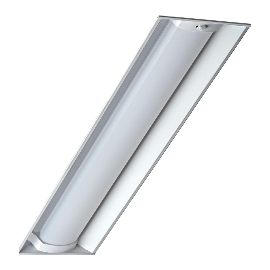
• The ZR-LDE1/LDE5 Series of recessed troffers is for non-insulated
ceiling applications using T-Bar ceiling grid, drywall grid adaptors,
and suspended mount.
• Designed for use in 120-277V 50-60 Hz protected circuit (fuse box,
circuit breaker). Supply wire sized as per NEC or governing code(s),
90C rated.
• Make sure to cap off all unused leads.
TO INSTALL:
1
1 of 4
Specification Troffers with Emergency Driver and Removable Lens
T-Bar Clips
Lutron EcoSystem Controls
Includes: ZR14-LDE1/LDE5, ZR22-LDE1/LDE5, ZR24-LDE1/LDE5
ZR14-LDE1/LDE5
ZR22-LDE1/LDE5
ZR24-LDE1/LDE5
• Lens and removable end cap may shift during installation. Press
center of lens to engage magnet strip and push the end cap against
the end panel to eliminate the gap after installation.
• IMPORTANT: To avoid damage to the lens or housing during
installation, make sure fixture is supported near the centers of both
long sides of the housing when lifting. Do not lift fixture from one
end only.
T-Bar Clip Hole
ZR Series with
INSTALLATION INSTRUCTIONS
INSTRUCTIONS D'INSTALLATION
T- BAR CEILING MOUNTING
STEP 1:
Bring the ZR troffer into the T-bar
ceiling panel. See Figure 1 for location
of the T-bar clips on end panels of
troffer.
STEP 2:
Bend clips upward and rotate outward
to engage with T-bar support grid. See
Figure 2. Secure luminaire to grid in
compliance with state and local codes.
LPN00678X0006A0_B
Advertisement
Table of Contents

Subscribe to Our Youtube Channel
Related Manuals for CREE LIGHTING ZR Series


Summary of Contents for CREE LIGHTING ZR Series
- Page 1 ZR Series with Lutron EcoSystem Controls Specification Troffers with Emergency Driver and Removable Lens Includes: ZR14-LDE1/LDE5, ZR22-LDE1/LDE5, ZR24-LDE1/LDE5 INSTALLATION INSTRUCTIONS IMPORTANT SAFEGUARDS INSTRUCTIONS D’INSTALLATION When using electrical equipment, basic safety precautions should always be followed including the following: READ AND FOLLOW ALL SAFETY...
-
Page 2: Suspended Mounting
Junction Box Cover T-Bar Clips bent upward, rotated outward, and engaged with the grid AC Wiring Ceiling Large Trim Ring Chamber Dimming Wiring Chamber Test Switch Small Trim Ring End Cap DO NOT Rotate Lens Into This Arrow Marked Zone End Cap Arrow Marks SUSPENDED MOUNTING... - Page 3 Fixed End Cap EMERGENCY DRIVER CHECK FCC NOTICE NOTE: For short-term testing of the emergency function, the battery CAUTION: Changes or modifications not expressly approved could void must be charged for at least one hour. The emergency driver must be your authority to use this equipment.
-
Page 4: Electrical Connections
AC power is supplied ON Switch © 2020 Cree Lighting, A company of IDEAL INDUSTRIES. All rights reserved. For informational purposes only. Content is subject to change. See www.creelighting.com/warranty for warranty and specifications. Cree and the Cree logo are ®... -
Page 5: Medidas De Seguridad Importantes
Serie ZR con controles Lutron EcoSystem Luminarias fluorescentes de especificación con controlador de emergencia y lentes extraíbles Incluye: ZR14-LDE1/LDE5, ZR22-LDE1/LDE5, ZR24-LDE1/LDE5 INSTRUCCIONES DE INSTALACIÓN MEDIDAS DE SEGURIDAD IMPORTANTES INSTRUCTIONS D’INSTALLATION Al usar aparatos eléctricos, siempre deben seguirse ciertas medidas básicas de seguridad, incluidas las siguientes: LEA Y SIGA TODAS LAS INSTRUCCIONES DE SEGURIDAD... - Page 6 Tapa de la caja de conexiones Clips de la barra en T doblados hacia arriba, girados hacia afuera y enganchados con la rejilla Cámara de Anillo de ajuste grande Cielo raso cableado de CA Cámara de cableado del atenuador Interruptor de prueba Anillo de ajuste pequeño Tapón NO gire el lente...
- Page 7 Tapón fijo VERIFICACIÓN DEL CONTROLADOR DE EMERGENCIA AVISO DE LA FCC NOTA: Para prueba a corto plazo de la función de emergencia, la batería PRECAUCIÓN: Los cambios o las modificaciones no aprobados podrían se deberá cargar durante una hora como mínimo. El controlador de anular su autoridad para usar este equipo.
-
Page 8: Conexiones Eléctricas
CA. Interruptor de ENCENDIDO © 2020 Cree Lighting, una empresa de IDEAL INDUSTRIES. Todos los derechos reservados. Para fines informativos únicamente. El contenido está sujeto a cambios. Visite www.creelighting.com/warranty para ver la garantía y las especificaciones. Cree y el logo de Cree son marcas registradas de Cree, Inc. -
Page 9: Mesures De Sécurité Importantes
Série ZR avec technologie SmartCast ® Plafonniers spéciaux avec pilote d'urgence et lentille amovible ZR14-SC1, ZR22-SC1 et ZR24-SC1 MESURES DE SÉCURITÉ IMPORTANTES INSTRUCTIONS D’INSTALLATION INSTALLATION INSTRUCTIONS Lorsque vous utilisez un équipement électrique, vous devez toujours respecter les règles de sécurité élémentaires, notamment les suivantes : LISEZ ET SUIVEZ TOUTES LES CONSIGNES DE SÉCURITÉ... - Page 10 ÉTAPE 8 : ® ÉTAPE 3 : Assurez-vous que la DEL bleue WIM clignote REMARQUE : Cree Lighting recommande de Raccordez le luminaire selon la section par séquence de deux fois de suite. Sinon, consulter le guide de déploiement sans fil de «...
-
Page 11: Dépannage
Si la lumière ne répond pas, utilisez l’outil de ÉTAPE 2 : La DEL sur la face avant de l’appareil fonctionne configuration Cree Lighting pour vérifier la Relâchez le bouton Réinitialiser pendant 1 seconde dans les niveaux du groupe de risque 1 selon CEI configuration. -
Page 12: Raccordements Électriques
CA rétablie. Interrupteur MARCHE © 2020 Cree Lighting, une société d'IDEAL INDUSTRIES. Tous droits réservés. À titre informatif seulement. Le contenu est sujet à changement. Consultez www.creelighting.com/warranty pour la garantie et les spécifications. Cree et le logo ®...
Need help?
Do you have a question about the ZR Series and is the answer not in the manual?
Questions and answers