Table of Contents
Advertisement
Quick Links
Advertisement
Table of Contents

Related Manuals for ITT FLYGT BWS Series


Summary of Contents for ITT FLYGT BWS Series
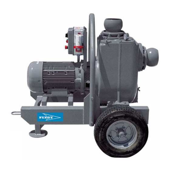
- Page 1 Installation, Care and Maintenance Self-priming centrifugal pumps...
-
Page 2: Table Of Contents
CONTENTS Care and Maintenance ........9 Safety ..............2 Inspection ............9 Warranty ............4 Replacing worn-out parts ....... 10 Product description .......... 4 Fault tracing ........... 13 Transportation and storage ......5 Service log ............14 Installation ............5 Operation ............ - Page 3 Unilateral modification and spare parts manufacturing Modifications or changes to the unit/installation should only be carried out after consulting ITT Flygt. Original spare parts and accessories authorized by the manufacturer are essential for compliance.
-
Page 4: Warranty
- that genuine ITT Flygt parts are used. or workmanship. Hence, the warranty does not cover faults caused - that the faults are reported to ITT Flygt or ITT Flygt’s by deficient maintenance, improper installation, representative during the warranty period. -
Page 5: Transportation And Storage
TRANSPORTATION AND STORAGE The pumping unit may be transported and stored in During handling on site, ensure a horizontal position. that the diesel tank (fitted on pumping unit base stand) is not Always lift the pumping unit subjected to impact or abrasion by its lifting system;... - Page 6 Put the pump in a horizontal Pumping unit with electric motor position. The suction pipe must be the straightest possible. It’s The user must protect the free end , at a distance of, at electrical power supply line least, twice the diameter from and the pumping unit against the bottom of the excavation, is short circuits and overloads by...
-
Page 7: Operation
OPERATION Before starting Check that the visible parts of the pump and installation are undamaged and in good condition. Before starting work on the pump, make sure that the pump cannot be energized In case of emergency, stop the pumping unit via the mushroom- head push button on the control panel (electrical motor) or via the lever stop system (diesel... - Page 8 How the pump works - Clogged "re-circulation" pipe (Tab.1, part. 1), Check through cleaning door (Tab. 1, part. 2) with pump not working. - Air passing through the mechanical seal. This can vacuum pump float be noticed thanks to water seepages from the mechanical seal when the pump is not working.
-
Page 9: Care And Maintenance
CARE AND MAINTENANCE ITT Flygt recommends a preventive maintenance Inspection (version with oil vacuum program based on Intermediate and major Services at pump) regular intervals. The time between Major Service could vary - Drain the condensate in the oil tank (Tab. 4, considerably depending on operating conditions and part.10), through the cock at least once a day. -
Page 10: Replacing Worn-Out Parts
The following points are important in connection WARNING! The oil chamber may be under pressure. with work on the pump. Hold a rag over the filling plug to prevent splatter. The pump is designed for use with liquids which WARNING! Proceed as follows if fluid have splashed can be a health risk. - Page 11 Use sleeves so as to avoid any contact with lapped surface and get regular and uniform thrust. Before assembling the parts, clean the seal and sliding counterface faces thoroughly. Standard seal may be used for impure water. For other liquids refer to ITT Flygt.
- Page 12 Replacing front and rear wear plate Remove all screws (Tab.7, part.1), pull out the wear plate (Tab.7, part.2). For reassembly, work in reverse and make sure that seat is perfectly clean (Tab. 8, part.3). Impeller and wear plates Check that measurements on the pump do not differ greatly from the following ones.A difference would imply reduced capacity and hydraulic efficienty as well as stalling the engine because of friction on the...
-
Page 13: Fault Tracing
FAULT TRACING Fault tracing should be performed with the machine Use the following checklist as an aid to fault tracing. in stand-by ensuring that the pumping unit cannot It is assumed that the pump and installation have re-start, even accidentally. been carried out as instructed. -
Page 14: Service Log
SERVICE LOG Pump N°. Hours of operation Most recent Remarks Sign. service date... - Page 15 Self-priming centrifugal pump 01.02.Eng.09.04...
Need help?
Do you have a question about the FLYGT BWS Series and is the answer not in the manual?
Questions and answers