
Related Manuals for Smartrise Magnetek L1000A


Summary of Contents for Smartrise Magnetek L1000A
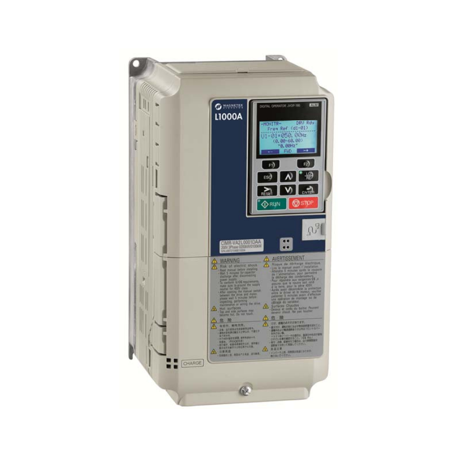
- Page 1 RIVE TARTUP ANUAL Magnetek L1000A Drive Permanent Magnet Installation www.smartrise.us | 2601 Fair Oaks Blvd., Sacramento, CA 95864 | 916.457.5129...
- Page 2 Magnetek L1000A Drive EQUIPMENT/SETTINGS VERIFICATION Verify that the Job Specification parameter table on the drawings “Sheet 1: Getting Started” matches the actual equipment. Below is a sample table showing the important values that will affect operation. Motor Motor Motor Volts...
- Page 3 CONTROLLER GROUNDING REQUIREMENTS NOTE – For the controller to function properly it is very important to provide proper building ground connections to the controller. Examples of a proper building-to-controller ground connection is to attach the ground cable to: The street side of the incoming water main. ...
- Page 4 WIRING – (Check off box when complete) ** Refer to the Appendix for the following connections ** Power – (Sheet 3: Machine Room connections) Connect main line power to terminal block L1/L2/L3. Connect the ground wire to the yellow/green terminal block next to L1-L3.
- Page 5 CONSTRUCTION – (Sheet 1: Construction) The following instructions are from the job drawings: “Sheet 1 – Construction”. Refer to the job’s specific drawings for connections. Construction Box (Sample) 24VDC connections to SRU board IOs 120VAC connections to DIN Rail terminals Emergency brake power 24v DC connections...
-
Page 6: Final Setup
(Check off box when complete) Apply external power by closing the main disconnect. Close the L1/L2 breaker, the M24, PS, BR and EBR breakers. Verify that the LCD on the Smartrise board and the Magnetek Drive come on. Down = ON... - Page 7 o Use the Up / Down Arrow keys and move the asterix to MISC and press the enter key. SETUP Local Outputs Security *Misc o BYPASS TERM LIMITS should be the first item listed. If it’s not there use the Up / Down Arrow keys and move the asterix to BYPASS TERM LIMITS and press the enter key.
- Page 8 The three “Auto Tunes” required are: Motor Tuning, 1 Phase of Encoder Tuning and 2 Phase of Encoder Tuning. ** During the alignment process the Smartrise SRU board will display several faults. These are normal and won’t affect the alignment procedure. ** Stationary Motor Auto-Tuning 1) Install a temporary jumper between H1 on the drive and REF on the DIN rail.
- Page 9 INPUTTING MOTOR DATA SAMPLE 1) If the data in the drive doesn’t match the existing equipment, use the following procedures to correct the values: a) Press UP arrow key to access the motor output power parameter T2-04. b) Press ENTER key to view the default setting. c) Press F1 (left), F2 (right), RESET, UP and DOWN arrow keys to enter the motor power nameplate data in kW –...
-
Page 10: Operation
No Faults Make sure the car is moving without triggering a fault either on the Smartrise SRU or the drive. If the SRU board displays a “Drive Fault” on the SRU, look at the drive to see what the fault is. -
Page 11: Troubleshooting
WRONG DIRECTION 1. If the car is moving in the wrong direction: a. On the Smartrise controller board make sure that IO 521 comes on when commanding the UP direction and IO 522 comes on when commanding the DOWN direction. - Page 12 APPENDIX Terminal Locations Main Line terminals L1/L2/L3 terminals Terminal / Card location on Motor PG card Brake terminals terminal T1/T2/T3 block Encoder wiring terminals...
Need help?
Do you have a question about the Magnetek L1000A and is the answer not in the manual?
Questions and answers