Chapters
Table of Contents

Related Manuals for Electrolux E9BSGLIUFE


Summary of Contents for Electrolux E9BSGLIUFE
- Page 1 SPARE PARTS DIAGRAM FOR Boiling Pan First Choice Group Blakeney Way, Kingswood Lakeside Cannock, Staffs, WS11 8LD TEL: 01543 577778 FAX: 01543504141 Email: enquires@firstchoice-cs.co.uk Web: www.firstchoice-cs.co.uk...
- Page 2 CATALOGO PARTI DI RICAMBIO SPARE PARTS CATALOGUE PENTOLA RETTANGOLARE 250LT GAS ELECTROLUX PROFESSIONAL INDIRETTO E900XP RECTANGULAR PAN 250LT INDIR. GAS HEATING E900XP PNC Factory Model Ref Description Descrizione 391105 E9BSGLIUFE a 250LT GAS RECT.BOILING PAN‐INDIR.HEATING PENTOLA RETTANGOLARE 250L GAS A RISC. INDIRETTO 392105 Z9BSGLIUFE c 250LT GAS RECT.BOILING PAN‐INDIR.HEATING PENTOLA RETTANGOLARE 250L GAS A RISC. INDIRETTO 393105 A9BSGLIUFE e ...
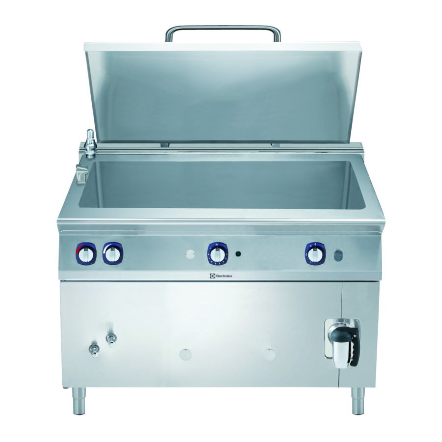
- Page 3 Vista generale / Main view DA N° DI FABBRICA 2441.0251 FROM SERIAL NR. EDIZIONE/ ISSUE 10‐12 DOC. Nr. 59785GG00. 938034911000 2 ...
- Page 4 ICOS ELECTROLUX DESCRIZIONE DESCRIPTION CODE CODE 17450 0C7525 GHIERA ACQUA CALDA HOT WATER KNOB RING 17432 0C7531 GHIERA ACQUA CALDA HOT WATER KNOB RING 17449 0C6802 GHIERA ACQUA FREDDA COLD WATER KNOB RING 7431 0C7385 GHIERA ACQUA FREDDA COLD WATER KNOB RING...
- Page 5 ICOS ELECTROLUX DESCRIZIONE DESCRIPTION CODE CODE 15564 0C5292 PIEDE BASE TONDA ACC. INOX FILETTO M10 ROUND BASE S/S LEG M10 FITTING 16994 0C3190 PRESSOSTATO DI LAVORO PRESSURE SWITCH 17097 0C8640 FLESSIBILE ½”F X ½”F - L=500 FLEX. HOSE ½”F X ½”F - L=500...
- Page 6 DOC. NO. 5958 9AY00 Edition 1 01.2013 IT+CH INSTALLAZIONE, USO E MANUTENZIONE APPENDICE: Dati tecnici GB+IE INSTALLATION, OPERATION AND MAINTENANCE APPENDIX: Technical data AT+DE+CH INSTALLATION, GEBRAUCH UND WARTUNG ANHANG: Technische Daten FR+BE+CH INSTALLATION, EMPLOI ET ENTRETIEN APPENDICE: Caractéristiques techniques INSTALACIÓN, USO Y MANTENIMIENTO APÉNDICE: Datos técnicos INSTALLATIE, GEBRUIKS EN ONDERHOUSAAN WIJZINGEN BIJLAGE: Technische gegevens...
- Page 7 DOC. NO. 5958 9AY00 Edition 1 01.2013 TARGHETTA CARATTERISTICHE PLACA DE CARACTERISTICAS CHAPA DE CARATERÍSTICAS ΠINAKIΔA TEXNIKΩN DATA PLATE PLAATJE MET KENMERKEN GERÄTESCHILD DATASKYLT ARVOKILPI PLAQUETTE SIGNALETIQUE TYPEPLADE TYPESKILT...
- Page 8 DOC. NO. 5958 9AY00 Edition 1 01.2013...
- Page 9 DOC. NO. 5958 9AY00 Edition 1 01.2013...
- Page 10 DOC. NO. 5958 9AY00 Edition 1 01.2013...
-
Page 11: Table Of Contents
DOC. NO. 5958 9AY00 Edition 1 01.2013 CONTENTS PAGE INSTALLATION INSTRUCTIONS ……............17 GENERAL WARNINGS…................17 COMPLIANCE WITH EEC DIRECTIVES............17 DATA PLATE……………………..............17 TRANSPORT AND STORAGE................. 18 Transport......................18 Storage…………….................... 18 INSTALLATION…....................18 PLACE OF INSTALLATION................18 POSITIONING…….................... 18 5.2.1 Unpacking…….……………………….............. -
Page 12: Iinstallation Instructions
DOC. NO. 5958 9AY00 Edition 1 01.2013 I - INSTALLATION INSTRUCTIONS • People under the effects of drugs, alcohol, 1 - GENERAL WARNINGS medicines compromising their mental alertness • This equipment must be installed by skilled cannot use the equipment nor carry out any personnel according to manufacturer’s instructions. -
Page 13: Transport And Storage
DOC. NO. 5958 9AY00 Edition 1 01.2013 4 - TRANSPORT AND STORAGE 5.2.2 - Positioning • Handle the equipment with care to avoid any 4.1 - Transport damage or danger for people. Use a pallet for The equipment is packed in a wooden crate that can handling and positioning. -
Page 14: Assembling The Safety Valve
DOC. NO. 5958 9AY00 Edition 1 01.2013 5.2.5 - Assembling the safety valve (Fig. 9) CAUTION! Using water with different technical characteristics from those specified above will • Wrap some Teflon tape or a specific sealant invalidate the product warranty. around the threaded connection ¾”M projecting When removing scales, do not use poly- from the shelf. -
Page 15: Connection With Gas Network
DOC. NO. 5958 9AY00 Edition 1 01.2013 of the power cord can be gained after the following CAUTION! operations: Before lighting the burners, make sure that the • Remove the front panel. jacket is filled with water up to the maximum level •... -
Page 16: Replacing The Nozzle Of Pilot Burner
DOC. NO. 5958 9AY00 Edition 1 01.2013 desired type of gas, complying with what 8 - MAINTENANCE indicated in Table 4. All the components having to be serviced are • The nozzle diameter is indicated in hundredths of accessible from the front side of the equipment mm on the nozzle body. -
Page 17: Operating Instructions
DOC. NO. 5958 9AY00 Edition 1 01.2013 Sparker plug (Fig. 6 "1") Gas valve (Fig. 5) • Remove the front panels. • Remove the knobs and the control board. • Disconnect the cable from the plug. • Unscrew the pipe of pilot burner “2” and of •... -
Page 18: Filling The Jacket With Water
DOC. NO. 5958 9AY00 Edition 1 01.2013 flame, release the knob: the flame must go on CAUTION burning. If this is not the case, repeat these Never set the equipment at work before filling the operations. jacket with water. • The lighting of pilot burner can be observed through Not complying with this standard would provoke inspection ports “O". -
Page 19: Cleaning And Maintenance
DOC. NO. 5958 9AY00 Edition 1 01.2013 • Weight-loaded safety valve “H”: being adjusted at 50 • The equipment must undergo a total check kPa (0,5 bar) it starts allowing steam to exhaust as periodically (at least once in a year). The efficiency the pressure in the jacket approaches this value. - Page 20 Liquid gas G31 2 x 205 1 x 14 1 x 65 1 x 170 Table 4 - Nozzles MODEL E9BSGLIUFE - Z9BSGLIUFE - A9BSGLIUFE Type of gas Nozzles of Nozzle of Nozzle of By-pass Air position of main burner...
- Page 21 CONTENTS JOINING APPLIANCES / TABLES ............................2 II. DATAPLATE and TECHNICAL DATA............................23 III. FOREWORD ....................................24 IV. INSTALLATION ..................................25 1. GENERAL INFORMATION ................................. 25 2. TRANSPORT, HANDLING AND STORAGE ..........................27 3. INSTALLATION AND ASSEMBLY ............................... 28 4. FUME EXHAUST ..................................29 5.
-
Page 22: Dataplate And Technical Data
II. DATAPLATE and TECHNICAL DATA ATTENTION This manual contains instructions relevant to various appliances. See the dataplate located under the control panel to identify the appliance (see fig. above). TABLE A - Gas/electrical appliance technical data - GB +9BRGHMOF0 +9BRGJMPF0 +9BREHMOF0 +9BREJMPF0 MODELS... -
Page 23: Foreword
III. FOREWORD The installation, use and maintenance Manual (hereinafter Manual) provides the user with information necessary for correct and safe use of the machine (hereinafter “machine” or “appliance”). The following must not be considered a long and exacting list of warnings, but rather a set of instructions suitable for improving machine performance in every respect and, above all, preventing injury to persons and animals and damage to property due to improper operating procedures. -
Page 24: Installation
Words further explaining the type of hazard are placed Manufacturer next to the symbols in the text. The warnings are intended Electrolux Professional SPA or any other service centre to guarantee the safety of personnel and prevent damage authorised by Electrolux Professional SPA. - Page 25 I ..........dust and water protection rating the country of use. CE ........... CE marking Electrolux Professional SPA declines any liability for any AB ........... gas safety certificate number inaccuracies contained in the manual, if due to printing or N ..........certification group translation errors.
-
Page 26: Transport, Handling And Storage
1.10 PERSONAL PROTECTION EQUIPMENT The machine must only be transported, handled and stored Given below is a summary table of the Personal Protection by qualified personnel, who must: Equipment (PPE) to be used during the various stages of the - have specific technical training and experience in the use machine’s service life. -
Page 27: Installation And Assembly
2.5 TRANSLATION 3.1 CUSTOMER’S RESPONSIBILITIES The operator must: The Customer must: • have a general view of the path to be followed; - prearrange a high-sensitivity manual-reset differential • stop the manoeuvre in case of hazardous situations. thermal-magnetic switch. For information regarding the electrical connection, refer to par. -
Page 28: Fume Exhaust
NOTE 4.1. FUME EXHAUST FOR TYPE “A1” APPLIANCES PERMANENT CONNECTION: the device lockable Position type “A1” appliances under an extractor hood to in the open position must be accessible even after ensure removal of fumes and steam produced by cooking. the appliance is installed in its place. - Page 29 • The gas supply line must ensure the gas flow necessary for 5.1.5. PRIMARY AIR CHECK full operation of all the appliances connected to the system. The primary air is correctly adjusted when the flame does A supply line with insufficient flow will affect correct operation not “float”...
-
Page 30: Safety Thermostat
6. WATER CONNECTION 5.2. ELECTRICAL CONNECTION (Fig. 4A-4B). Connection to the power supply must be carried out in compliance with the regulations and provisions in force in the ATTENTION! country of use. The water connection must be carried out by a specialised technician. -
Page 31: Braiser Use
V I N S T R U C T I O N S F O R 1.2. GAS MODELS The burner ignition knob “V” (on front panel) has 3 positions: OPERATOR FOR NORMAL MACHINE USE 90°-300° temperature power regulator 1. BRAISER USE General precautions •... - Page 32 1.3. ELECTRIC MODELS 1.5 LIFTING THE TANK NOTE: Lift the lid before lifting the tank. The ignition knob ‘V” (front panel) has 3 positions: 90°-300° temperature power regulator Automatic lifting Switching on Use the controls on the right of the control panel for power- •...
-
Page 33: Cleaning And Maintenance
sicurezza. È vietato usare acqua per spegnere gli incendi (esposto sulle parti C L E A N I N G A N D 1.2.2. SAFETY SIGNS TO BE PLACED ON THE MACHINE elettriche). OR NEAR ITS AREA MAINTENANCE RISK MEANING 1 GENERAL SAFETY RULES BURN HAZARD ATTENTION! -
Page 34: Normal Machine Use
2. NORMAL MACHINE USE ATTENTION! The previously described actions are prohibited! 2.1 CHARACTERISTICS OF PERSONNEL TRAINED FOR 1.2.6 RESIDUAL RISKS NORMAL MACHINE USE The machine has several risks that were not completely The Customer must make sure the personnel for normal eliminated from a design standpoint or with the installation machine use are adequately trained and skilled in their of adequate protection devices. - Page 35 3.1 ROUTINE MAINTENANCE 3.4 EXTERNAL PARTS Frequently check the state of the power cable and, if necessary, SATIN-FINISH STEEL SURFACES (daily) request the assistance of the specialised technician to replace • Clean all steel surfaces: dirt is easily removed when it has it;...
- Page 36 3.8 EXTRAORDINARY MAINTENANCE. • To replace the detection electrode, remove the left side, loosen the fixing screws and remove the components. ATTENTION! USE SUITABLE PERSONAL PROTECTION EQUIPMENT WHEN CARRYING OUT ANY EXTRAORDINARY MAINTENANCE OPERATION. Extraordinary maintenance must be carried out by specialised personnel, who can ask the manufacturer to supply a servicing manual.
- Page 37 POWER REGULATOR AND WORK THERMOSTAT - check for any oxidised electrical components or parts; if • Remove the control panel and replace the component. necessary, replace them and restore the initial conditions; - check the structure and welded joints in particular; - check and replace bolts and/or screws, also checking for SAFETY THERMOSTAT •...
-
Page 38: Machine Disposal
AUSTRALIA ATTENTION! For service and spare parts, please contact: WORK ON THE ELECTRICAL EQUIPMENT Electrolux - Tom Stoddart Pty Ltd MUST ONLY BE CARRIED OUT BY A QUALIFIED Zanussi - JL Lennard Pty Ltd ELECTRICIAN, WITH THE POWER SUPPLY DISCONNECTED.
Need help?
Do you have a question about the E9BSGLIUFE and is the answer not in the manual?
Questions and answers