Table of Contents
Advertisement
Quick Links
Operator's Manual
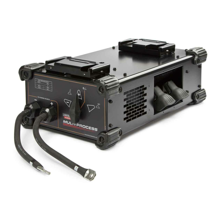
Multi Process Switch
For use with machines having Code Numbers:
K3091-1
IM10505
| Issue D ate Apr-19
© Lincoln Global, Inc. All Rights Reserved.
Need Help? Call 1.888.935.3877 to talk to a Service Representative
Hours of Operation: 8:00 AM to 6:00 PM (ET) Mon. thru Fri.
After hours? Use "Ask the Experts" at lincolnelectric.com
A Lincoln Service Representative will contact you no later than the following business day.
For Service outside the USA: Email: globalservice@lincolnelectric.com
Register your machine:
www.lincolnelectric.com/registration
Authorized Service and Distributor Locator:
www.lincolnelectric.com/locator
Save for future reference
Date Purchased
Code: (ex: 10859)
Serial: (ex: U1060512345)
Advertisement
Table of Contents

Related Manuals for Lincoln Electric K3091-1


Summary of Contents for Lincoln Electric K3091-1
- Page 1 Authorized Service and Distributor Locator: www.lincolnelectric.com/locator Save for future reference Date Purchased For use with machines having Code Numbers: K3091-1 Code: (ex: 10859) Serial: (ex: U1060512345) IM10505 | Issue D ate Apr-19 © Lincoln Global, Inc. All Rights Reserved.
- Page 2 Thank you for selecting a quality product by Lincoln Elec tric. Please Examine Carton and Equipment For Damage Immediately - When this equipment is shipped, title passes to the purchaser upon receipt by the carrier. Consequently, claims for material damaged in shipment must be made by the purchaser against the transportation company at the time the shipment is received.
-
Page 3: Table Of Contents
TABLE OF CONTENTS SAFETY ..........................4 TECHNICAL SPECIFICATIONS......................10 NAME PLATE SYMBOL DEFINITIONS.....................11 GENERAL DESCRIPTION AND OPERATION..................11 MOUNTING ..........................12 GENERAL SET-UP.........................12 SET-UP FOR WIRE FEEDER WELDING (AUTOMATIC OR SEMIAUTOMATIC PROCESSES ....13 SET-UP FOR STICK WELDING OR AIR/CARBON ARC WELDING PROCESSES ........13 INSTALL AIR DUCT ........................14 WIRING DIAGRAM ........................15 PARTS LIST ..................PARTS.LINCOLNELECTRIC.COM CONTENT/DETAILS MAY BE CHANGED OR UPDATED WITHOUT NOTICE. -
Page 4: Safety
CSA Standard W117.2-1974. A Free copy of “Arc Welding Safety” booklet E205 is available from the Lincoln Electric Company, 22801 St. Clair Avenue, Cleveland, Ohio 44117-1199. 2.c. Exposure to EMF fields in welding may have other health effects which are now not known. - Page 5 WARNINGS ELECTRIC SHOCK CAN KILL. ARC RAYS CAN BURN. 3.a. The electrode and work (or ground) circuits are electrically “hot” when the welder 4.a. Use a shield with the proper filter and cover plates to protect your eyes from is on. Do not touch these “hot” parts with your bare skin or wet clothing. Wear sparks and the rays of the arc when welding or observing open arc welding.
- Page 6 WARNINGS WELDING AND CUTTING SPARKS CAN CYLINDER MAY EXPLODE IF DAMAGED. CAUSE FIRE OR EXPLOSION. 7.a. Use only compressed gas cylinders containing the correct shielding gas for the process used and properly operating regulators designed for the gas and 6.a. Remove fire hazards from the welding area. If this is not possible, cover them to pressure used.
- Page 7 WARNINGS...
- Page 8 Welding equipment should be connected to the public supply system according to the manufacturer’s recom- Lincoln Electric equipment. It is designed for industrial and professional use. mendations. If interference occurs, it may be necessary to take additional precautions such as filtering of the system.
- Page 9 WARNINGS 7. Quand on ne soude pas, poser la pince à une endroit isolé de la masse. Un court-circuit PRÉCAUTIONS DE SÛRETÉ accidental peut provoquer un échauffement et un risque d’incendie. 8. S’assurer que la masse est connectée le plus prés possible de la zone de travail qu’il est Pour votre propre protection lire et observer toutes les instructions et les précautions de sûreté...
-
Page 10: Technical Specifications
MULTI-PROCESS SWITCH TECHNICAL SPECIFICATIONS Multi-Process Switch - K3091-1 OUTPUT AND DUTY CYCLE RATINGS OF THE MULTI-PROCESS SWITCH: Duty Cycle Volts Amps 60 % 100 % Amperage and duty cycle are increased when the Multi-Process Switch is con- nected to a FLEXTEC™ 650 using the supplied air duct: AMPERAGE AND DUTY CYCLE - FLEXTEC™... -
Page 11: Name Plate Symbol Definitions
MULTI-PROCESS SWITCH INSTALLATION INSTALLATION generaL deSCrIPtIon and oPeratIon The Multi-Process Switch provides the ability to select between “Stick or Air/Carbon Arc” and SAFETY PRECAUTIONS “Automatic or Semiautomatic” processes, and a change of the “Automatic or Semiautomatic READ AND UNDERSTAND ENTIRE SECTION BEFORE OPERATING MACHINE. polarity without changing any electrical connections. -
Page 12: Mounting
MULTI-PROCESS SWITCH INSTALLATION mountIng See Figure A.2 generaL Set-uP See Figure A.3 Mount the Multi-Process Switch directly to the bottom of a compatible FLEXTEC™ series power 1. Welding cables must be of proper capacity for the current and duty cycle of immediate and source utilizing the quick lock mechanism shown in Figure A.2. -
Page 13: Set-Up For Wire Feeder Welding
MULTI-PROCESS SWITCH INSTALLATION Set-uP for WIre feeder WeLdIng (automatIC or SemIautomatIC Set-uP for StICK WeLdIng or aIr/CarBon arC WeLdIng ProCeSSeS ProCeSSeS See Figure A.4 See Figure A.5 1. Move the switch on the Multi-Process unit (Item A) to the left to set to either positive (+) or 1. -
Page 14: Install Air Duct
MULTI-PROCESS SWITCH INSTALLATION InStaLLatIon of aIr duCt on fLeXteC™ 650X for InCreaSed ratIngS Figure A.7 FOR INSTANCES WHERE THE WORK TERMINAL (LEFT SIDE) AND THE NEGATIVE TERMINAL (RIGHT SIDE) ARE TIED TOGETHER: If using both a stick and wire process, it may be desirable to only run one single cable to the work piece. -
Page 15: Wiring Diagram
MULTI-PROCESS SWITCH DIAGRAMS Right side / Stick / Carbon Arc gouge side Multi-process switch Multi Process rear Switch Front left side/ wire welding side... - Page 16 We respond to our customers based on the best information in our possession at that time. Lincoln Electric is not in a position to warrant or guarantee such advice, and assumes no liability, with respect to such information or advice. We expressly disclaim any warranty of any kind, including any warranty of fitness for any customer’s...
Need help?
Do you have a question about the K3091-1 and is the answer not in the manual?
Questions and answers