Zummo Z40 Technical Instructions
Hide thumbs
Also See for Z40:
- User manual (216 pages) ,
- Maintenance program (13 pages) ,
- Instructions manual (7 pages)
Advertisement
Quick Links
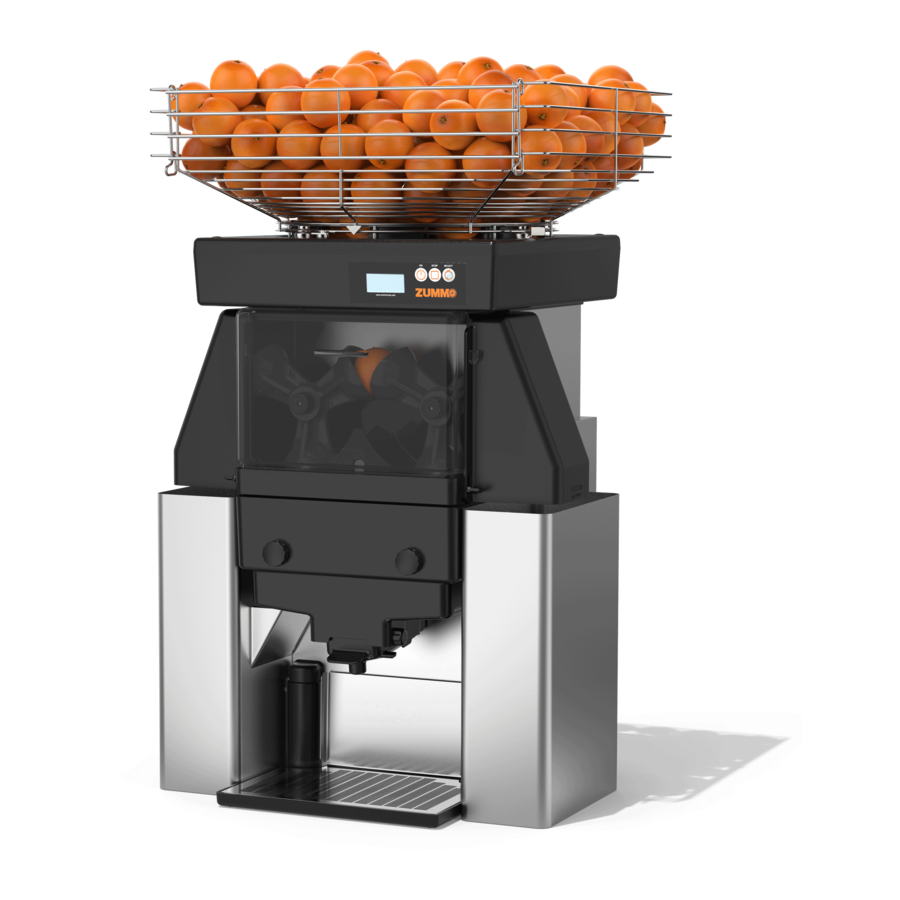
Z40
Technical Instructions
INDEX:
1.-
Error list.
2.-
Disassemble machine.
3.-
Dismantling of motor and gear box in Z40.
4.-
Assembly of gear box in Z40
5.-
Adjustment of pushing plate.
6.-
Replacement of cup shaft fixing ring.
7.-
Replacement of cup shaft.
8.-
Replacement of ball bearing.
9.-
Machine setup levels.
10.- Circuit diagram in Z40
11.- Feeder synchronization checking.
12.- Machine closing.
1.- ERROR LIST
1.1 Front cover not fitted correctly.
The display will show the following image:
The front cover has a magnet attached on the top. Once fitted in its position, the sensor placed
inside the hopper track base closes the safety circuit. The error message will then disappear,
allowing you to operate the machine.
1.1.1 Check that the magnet is on the front cover. If not there, replace the front cover.
1.1.2 If the magnet is on the front cover, disassemble the hopper track lid following the instructions
to open the machine from step #2. Once open, check there is electric continuity between
011307-05
1
Advertisement

Related Manuals for Zummo Z40


Summary of Contents for Zummo Z40
- Page 1 Technical Instructions INDEX: Error list. Disassemble machine. Dismantling of motor and gear box in Z40. Assembly of gear box in Z40 Adjustment of pushing plate. Replacement of cup shaft fixing ring. Replacement of cup shaft. Replacement of ball bearing. Machine setup levels.
- Page 2 Technical Instructions both connector terminals, with the help of a multimeter. If there is no continuity, you must change the magnet sensor. 2.1.1 If the magnet is on the front cover and there is continuity between the sensor terminals with the front cover in place, you must change the circuit board.
- Page 3 Technical Instructions 1.2.2 If you can hear the “click” but they do not close the safety circuit, disassemble the hopper track lid (follow instructions in step #2 to open the machine) and check if there is conductivity between pins 4 and 10 with the side covers correctly placed. If there is no conductivity, check which of the micro-switches is causing the failure.
-
Page 4: Motor Thermal Sensor
Technical Instructions In the same way as before, pushing the switch with your fingers, you should be able to hear the opening and closing “click”. If this error is shown while working, check that filter tray, self-service tray and tank are all correctly placed as they could have moved from its original position. - Page 5 Technical Instructions The squeezer tray balls are not fully screwed and the motor is then subject to a bigger effort. Check by sight and manually. The squeezer tray balls do not match the cup size. The cooling grill is being partially or completely blocked by any object. If the motor temperature seems not to be the reason of this error message when the machine is cold or the error message does not disappear once the machine has cooled down, check the following points:...
-
Page 6: Cycle Failure
Technical Instructions 1.5 Cycle failure The display will show the following image: The machine completes a cycle (a piece of fruit) every 1.5 seconds. Within this period of time, a signal is sent to the circuit board via a micro-switch that is triggered (opening and closing) by the right cup slide. - Page 7 Technical Instructions 1.5.2 Machine blocked: 1.5.2.1 The cup hits the front or the side of the squeezer tray. In case the cup nuts are not correctly tightened, they may loosen up, releasing the cups. When the cup is not fixed, it can get loose and hit the squeezer tray.
- Page 8 Technical Instructions 2.- DISASSEMBLE MACHINE (12 min). 1. Unplug the machine from the main power supply. 2. Remove the external basket by turning it slightly. 3. Unscrew the nut which is on top of the fruit classifier and take it out by pulling out. 4.
- Page 9 Technical Instructions 6. Remove the hopper track lid and unplug the cables from CPU board. 7. Remove the 2 top blanking plugs, unscrew the 4 screws to be able to remove the hopper track base and take the roof top closing off as well as the joint placed on the basket shaft. 8.
- Page 10 Technical Instructions 9. Loosen the supports 2-3 mm, unscrew the 2 screws that fix the body to the chassis and remove the body. 9. Loosen the front supports by 2-3mm, unscrew the 4 screws that affix the front to the chassis (two on the top and two more on the bottom) and remove the front by pulling out.
- Page 11 Technical Instructions 3.- DISMANTLING OF MOTOR AND GEAR BOX OF Z40 1. Disassemble the group that triggers the feeder by loosening the screws or nuts pointed out in pictures below. Unplug the cables from the capacitor 3. Remove the “M8x20” screw and the washers that fasten the connecting rod.
- Page 12 Technical Instructions 4. Incline the machine over the flat bar axis and remove the “M8x70” Allen screws placed on the bottom of the chassis that fasten the gear box to it. 5. Carefully remove the motor-gear box group. 6. Remove the belt. 011307-05...
- Page 13 Technical Instructions 7. Remove the “M6x16” hexagon head screw along with the two “T-9021 M6” washers and extract the lower pinion in order to be able to remove the copier group. 8. Remove the “T-933-M6x25 mm” hexagon head screws that fasten the motor support to the gear box.
- Page 14 Technical Instructions 4.- ASSEMBLY OF GEAR BOX OF Z40 ASSEMBLY OF GEAR BOX SUBSET AND MOTOR WITH COPIER AND CONNECTING Grease the gear box shaft (210405), ratio 15:1. Put the pulley 30L in (210408) Place the screw along with the welded washer (210428).
- Page 15 Technical Instructions Put in the motor base plate (210410), as shown in picture, leaving 2mm to the right edge of the gear box and as much as possible behind. Fasten the board to the gear box using 4 “T-933-M6x25mm” screws, 4 “T-9021 M6” washers and 4 “T-934 M6”...
- Page 16 Technical Instructions Assemble the motor over the silent-blocks with 4 “T-934-M6” nuts and 4 “T-9021-M6” washers. Put the “187L 050” belt. Straighten and stretch. ASSEMBLY OF GEAR BOX SUBSET AND MOTOR IN CHASSIS Grease the surface of the connecting rod making contact with the pushing plate, place the whole motor group along with the gear box, put the connecting rod in vertical position and put it into the bolt.
- Page 17 Technical Instructions Place the pinion backing (210301) with 1 “T-933-M6x16 mm” screw and 1 “T-934-M6” nut, fastening to the motor base. Assemble pinion-feeder subset. Affix the plate to the chassis using 2 “T-933-M6x16 mm” screws and 2 “T-9021-M6” washers. Put 2 T-9021-M6 washers in and 2 T-934-M6 nuts to affix the pinion support to the pinion backing.
- Page 18 Technical Instructions Place the upper pinion (Ref. 210307) (Part E) with the keyway completely vertical. Assemble the crown (Ref. 210309) (Part A) with the tooth matching the ø 5mm hole into the cone-shape pinion gap (Ref. 210308) (Part B). Check that keyways of parts D and E are completely vertical.
- Page 19 Technical Instructions 5.- ADJUSTMENT OF PUSHING PLATE (10 min) With the machine open, take the stainless steel slide cover off by removing the 6 screws that fasten it as shown in left picture. In machines with serial number 2143638 or higher, make sure the pushing plate is in horizontal position and check the screws shown in right picture.
- Page 20 Technical Instructions 7.- REPLACEMENT OF CUP SHAFT (10 min) To remove a cup shaft, you must remove the stainless steel plate covering the slides as previously explained. Release the wedge spring and disengage wedges. With the connecting rod in vertical position, release the screw that fastens the axis to the ratchet.
- Page 21 Technical Instructions Turn the motor pulley to allow the connecting rod to go down and make sure the wedge engages the ratchet properly. 8.- REPLACEMENT OF BALL BEARING (10 min) First, you must disassemble the gear box as shown in step #2. Once removed, you must release the screw from the blade slide using a 13mm hexagon shape key.
- Page 22 Technical Instructions On machines with serial number after 2143638, for change the copier bearing we don’t need to dismantle the gearbox. We can proceed like in the pictures below. First of all, we loose and remove the hexagonal bolt that fixes the upper side of the rod and then both Allen socket screws (Spotted in red) on the other side Once we have all the screws removed with the help of a nylon hummer and a lever for remove the pressing set easily.
- Page 23 Technical Instructions When we have the pressing set removed the rod will be free on the upper side and we can be able to move it towards right, moving the motor clockwise, until we have free access to the bearing below. Then we can proceed to change it easily and straightaway assemble it again.
- Page 24 Technical Instructions 9.- MACHINE SETUP LEVELS The maximum height the cup slides must reach is given by the screw affixed to the chassis, as shown in the picture. For machines with serial number 2140261 or higher, the measurement for the correct setup of the machine must be between 40.4 and 41 mm Once this measurement has been fixed, with the connecting rod in vertical position, you must check there is a distance of at least 1.5mm between wedge and ratchet, to make sure they...
- Page 25 Technical Instructions 10.- CIRCUIT DIAGRAM IN Z40 1. Fuse. 2. Bipolar switch. 3. Circuit board. 4. Motor. 5. Condenser. 6. Tray micro-switch. 7. Front cover magnetic sensor. 8. Lef side cover micro-switch. 9. Right side cover micro-switch. 10. Counter micro-switch 11.
- Page 26 Technical Instructions By turning the key we will allow the inner basket to rotate until both, central rod of outer basket and one of the rods that fasten the feeder sectors are aligned on the same plane, as shown in the following picture on the right side. When basket is as shown in left picture above, cups must remain vertical and facing up as shown in picture below.
- Page 27 Technical Instructions If not the case, disassemble the machine following the instructions in step #2 and adjust the operation of the feeder, following the instructions in section 4.3. If cups were correctly placed, check condition and position of fruit classifiers. 12.- MACHINE CLOSING (18 min) Reassemble the body set by inserting the tab in the interior side of the front.
- Page 28 Technical Instructions 2. Assemble base hopper track in machine. Accommodate wiring through the holes in base hopper track, putting the cables along the outside of the circle and releasing the lid fastening pieces, using 4 screws, 2 “I-7985-M4x30 mm” screws on the back side and 2 “I-7985-M4 x 12 mm”...
- Page 29 Technical Instructions 5. In case the legs had previously been removed, assemble the legs to the chassis. The front legs must have the support washers (210213) and will be adjusted to a height of 140mm, whereas the rear ones do not bear any washer and will be adjusted to 142mm. 6.
Need help?
Do you have a question about the Z40 and is the answer not in the manual?
Questions and answers