Chapters
Table of Contents

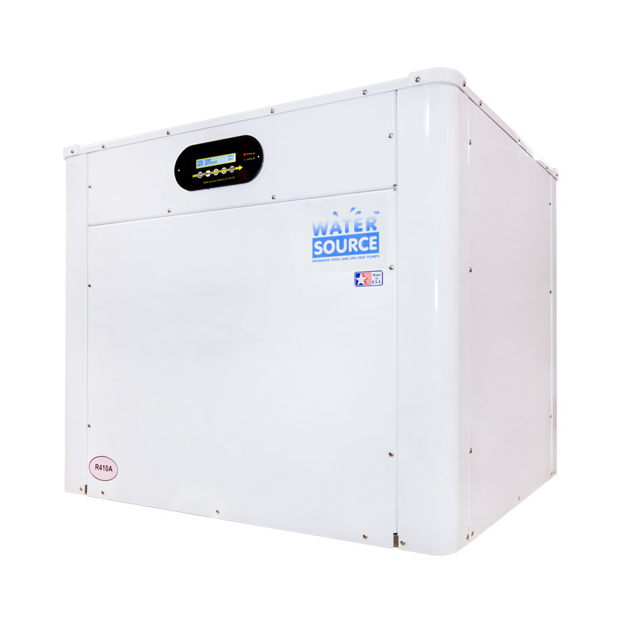
Related Manuals for Aquacal WATER SOURCE WS03


Summary of Contents for Aquacal WATER SOURCE WS03
- Page 1 ® AquaCal Installation Manual Important Read this document before operating / installing this product For additional product manuals and operation / installation procedures, please visit www.AquaCal.com LTP0116 REV 3.3 - (project rel 7.02)
-
Page 3: Table Of Contents
Table of Contents Contacting AquaCal AutoPilot, Inc. Safety Instructions 1 - Installation 1.1 Positioning Equipment 1.2 Clearances 1.3 Dimensions 1.4 Plumbing 1.4.a Plumbing Requirements 1.4.b Plumbing Diagrams (Water Source) 1.4.c Plumbing Diagrams (SunPower) 1.4.d Water Connections to Heat Pump 1.4.e In-Line Chlorine Feeders 1.4.f Water Flow Rates... - Page 4 3.3 Weights 3.4 Heating Recommendations 3.5 Cooling Recommendations 3.6 Available Accessories 3.7 ICM Digital 3-Phase Monitor 3.8 Schematics Schematic LTM0943 Schematic LTM0946 Schematic LTM0951...
-
Page 5: Contacting Aquacal Autopilot, Inc
Repair and service of heat pump must be performed by an authorized service center. Warranties may be voided if the equipment has been improperly installed, maintained or serviced. If service is deemed necessary, please contact AquaCal. See "Contacting AquaCal AutoPilot, Inc." above. SAFETY SIGNALS Throughout this document, safety signals have been placed where particular attention is required. - Page 6 Failure to heed the following may result in injury or death. WARNING Installation and repairs must be performed by a qualified technician. The heat pump contains refrigerant under pressure. Repairs to the refrigerant circuit must not be attempted by untrained and/or unqualified individuals. Service must be performed only by qualified HVAC technicians. Recover refrigerant before opening the system.
-
Page 7: Installation
1 - Installation Failure to heed the following may result in injury or death. WARNING Installation of this equipment by anyone other than a qualified installer can result in a safety hazard. The information contained throughout the "Installation" section is intended for use by qualified installation technicians familiar with the swimming Pool/Spa safety standards. -
Page 8: Positioning Equipment
They should be used to anchor the heat pump to the pad. ® If needed, contact AquaCal to obtain anchoring kit information. Please have the heat pump model number and serial number when requesting support. See "Identifying Model Specifications" on page 74. - Page 9 Water Source (Top View) Water Source (Side View) Page - 5...
-
Page 10: Dimensions
1.3 Dimensions (Water Source WS03, WS05) (Water Source WS10) Page - 6... -
Page 11: Plumbing
(SunPower SP05) 1.4 Plumbing 1.4.a Plumbing Requirements Failure to heed the following may result in damage to equipment. NOTICE Do not use glue on the threaded portion of the equipment’s unions. A glued-in-place union will prevent the equipment from being properly winterized. The heat pump must receive water flow within the specified minimum ranges under worst-case conditions such as a fouled water filter. -
Page 12: Plumbing Diagrams (Water Source)
The basic plumbing configurations for typical installations are shown. ® If the installation does not closely follow any of the supplied plumbing diagrams, AquaCal Technical Support is available for installation advice and guidance. Confirm water provided to the heat pump is clean and filtered. - Page 13 Multiple Water Source Heat Pump Configuration (Standard Pressures) Single Water Source Heat Pump Configuration (High-Pressure) Page - 9...
- Page 14 Multiple Water Source Heat Pump Configuration (High-Pressure) Water Source Heat Pump with Support Equipment Page - 10...
-
Page 15: Plumbing Diagrams (Sunpower)
The basic plumbing configurations for typical installations are shown. ® If the installation does not closely follow any of the supplied plumbing diagrams, AquaCal Technical Support is available for installation advice and guidance. Confirm water provided to the heat pump is clean and filtered. -
Page 16: Water Connections To Heat Pump
Connections to site plumbing are made via PVC solvent cement to the female slip socket of the plumbing unions. High-pressure units use joint compound on threaded copper connections. ® Plumbing unions are available from AquaCal Failure to heed the following may result in damage to equipment. NOTICE Do not use glue on the threaded portion of the equipment’s unions. - Page 17 Water Source WS03 and WS05 (Titanium Exchanger Only) Water Source WS03 and WS05 (Titanium / Cupronickel Exchanger Combination) SunPower SP05 (Titanium Exchanger Only) Page - 13...
-
Page 18: In-Line Chlorine Feeders
SunPower SP05 (Titanium / Cupronickel Exchanger Combination) 1.4.e In-Line Chlorine Feeders Place in-line chlorinators downstream from the heat pump and as low in elevation as possible. If an erosion type feeder is used, it is recommended that a Hartford Loop be installed to protect internal heat pump components. -
Page 19: Adjusting Water Flow Using Δt (Delta-T)
FLOW RATES MODEL SOURCE HEAT EXCHANGER TYPE MINIMUM MAXIMUM ® Titanium ThermoLink 20 GPM (75.7 L/min) 70 GPM (265 L/min) Source-Side WS05 Cupronickel 10 GPM (37.9 L/min) 18 GPM (68 L/min) ® Pool / Spa Titanium ThermoLink 30 GPM (113.6 L/min) 70 GPM (265 L/min) ®... - Page 20 3. Confirm that the filters leading to the heat pump are clean. 4. Adjust the valves controlling water headed towards the heat pump to the half-open position. 5. Adjust the valves controlling water leading away from the heat pump to a fully open position. 6.
-
Page 21: Geothermal Menus
Temperature differences are based on pool and source water temperatures of 69° to 75° F. (20.5° to 23.8° C) ® . See "Contacting For water temperatures outside this range, contact AquaCal AquaCal AutoPilot, Inc." on page 1. 1.4.h Geothermal Menus These menus are used when adjusting Water Flow Using ΔT (Delta-T). (See Adjusting Water Flow Using ΔT... -
Page 22: Maintaining Ability To Winterize
1.4.i Maintaining Ability to Winterize Do not glue the threaded portion of the unions. The unions are used to decouple the heat pump from the plumbing system during hard freeze conditions. Failure to heed the following may result in damage to equipment. NOTICE Do not use glue on the threaded portion of the equipment’s unions. -
Page 23: Electrical
In sizing power wiring, be especially aware of up-sizing requirements necessary due to wiring distances. Always satisfy applicable codes and standards. ® AquaCal heat pumps are designed to use copper conductors, only. Do not use aluminum wire. If multiple heat pumps are on-site, confirm that the multiple heat pump configuration has been utilized. See "Connecting Multiple Heat Pumps (Primary / Secondary)"... - Page 24 Surge Suppression The use of approved commercial surge protectors is strongly recommended. Sizing the Electrical Service Refer to equipment data plate for specific information required to size electrical service and over-current protection of the heat pump. Sizing is based on data plate information, wire size, wiring devices, and over- current protection per applicable local codes and standards.
- Page 25 PLEASE NOTE Standard ICM Digital Three-Phase Three-Phase Monitor Monitor The WS10 Water Source heat pump comes with an ICM phase-rotation monitor. All other three-phase models use the standard phase-rotation monitor. These monitors are located inside the electrical panel. The device protects the heat pump by preventing operation during abnormal voltage conditions.
-
Page 26: Incoming Power Access Holes
1.5.b Incoming Power Access Holes Water Source WS03, WS05 SunPower SP050 Water Source WS10 Page - 22... -
Page 27: Access Panels
1.5.c Access Panels Failure to heed the following will result in injury or death. DANGER Deactivate power while routing wiring to control board. Follow all National Electric Codes (NEC) and/or State and Local guidelines. (SunPower) (Water Source) 1.5.d Verifying Transformer Setting Transformer voltage must be confirmed and set correctly depending on the measured voltage found on the site. - Page 28 1. Turn heat pump on by adjusting the thermostat to call for heating or cooling. Example of heat pump If more than one heat pump is on-site, turn them all on. Allow time for all transformer heat pump compressors to activate. (Varies between models) 2.
-
Page 29: Three-Phase Adjustment
3. When heat pump starts, disconnect power and verify off. Then confirm all line voltage connections are securely tightened. Reconnect power. ® If the heat pump does not start, contact AquaCal for further assistance. See "Contacting AquaCal AutoPilot, Inc." on page 1. -
Page 30: External Equipment
1.6 External Equipment 1.6.a Connecting a Call Flex To support a direct connection to a call flex accessory, AquaCal ® heat pumps are equipped with optional terminal blocks on the microprocessor. The microprocessor is located on the low-voltage side of the electrical enclosure. - Page 31 Configure Call Flex Enter "Installer Menus", then proceed Page - 27...
- Page 32 Page - 28...
-
Page 33: Connecting A Source Water Relay Switch
5. Reattach heat pump access panel. 6. Apply power to heat pump. 1.6.c Connecting External Controllers to Heat Pump To support a direct connection to an external controller, AquaCal ® heat pumps are equipped with optional removable terminal blocks on the microprocessor. The microprocessor is located on the low-voltage side of the electrical enclosure. -
Page 34: Connecting Smart Bus Controllers
Failure to heed the following may result in damage to equipment. NOTICE Do not use an electric heater connection on external controllers for heat pump wiring. This can cause damage to external controllers, heat pumps, and pad equipment. This damage is NOT covered by warranty. The wire size connecting the external controller to the heat pump must be 22- gauge, 2-conductor, low-voltage wire. - Page 35 5. If dip-switch settings are required, configure them on the external controller now. Failure to heed the following will result in injury or death. DANGER Deactivate power to the external controller while setting dip-switches ® Example - Jandy AquaLink This external controller has dip switches. Confirm they are properly positioned to operate a heat pump.
- Page 36 Page - 32...
-
Page 37: Connecting Two-Wire Controllers (With Internal Thermostat)
SMART COMM FAULT 10. If after 45 seconds, the heat pump displays a " ": A. Confirm dip switches - If external controller uses dip switches, confirm switches are in the correct position. Otherwise, proceed to confirm wiring. a. Deactivate power to the external controller. b. - Page 38 Failure to heed the following may result in injury or death. WARNING This section is only for qualified installers who are familiar with the swimming pool and spa safety standards. The installer must be familiar with service industry techniques. 1. Deactivate power to heat pump. 2.
- Page 39 Page - 35...
-
Page 40: Connecting Gas Backup Heater To Heat Pump
1.6.d Connecting Gas Backup Heater to Heat Pump ® To support a direct connection to a gas backup heater, AquaCal heat pumps are equipped with optional terminal blocks on the microprocessor. The microprocessor is located on the low-voltage side of the electrical enclosure. - Page 41 Connections 1. Deactivate power to heat pump and gas heater. 2. Remove heat pump and gas heater's electrical access panels. Follow all National Electric Codes (NEC) unless State or Local guidelines supersede. 3. Route 22-gauge (minimum), 2-conductor, low-voltage wires from the gas heater to the low voltage side of the heat pump's electrical enclosure.
- Page 42 Configuring Gas Backup There are two different ways the gas backup heater can be configured. 24-hour mode - commonly used for commercial applications The circulation pump operates continuously. The gas heater will activate if the water temperature falls two degrees below the set temperature. When the set temperature is reached, the gas heater will be deactivated.
- Page 43 Page - 39...
- Page 44 Configure for Scheduled Mode Enter "Installer Menus", then proceed Page - 40...
-
Page 45: Connecting Multiple Heat Pumps (Primary / Secondary)
1.6.e Connecting Multiple Heat Pumps (Primary / Secondary) Up to 16 heat pumps can be connected and controlled from a primary heat pump. There are two reasons for using a multiple heat pump configuration: 1. Controlling multiple heat pumps from one location; the primary heat pump. 2. - Page 46 Failure to heed the following may result in damage to equipment. NOTICE The wire size connecting the heat pumps must be 22-gauge, 2-conductor, DO NOT CONNECT low-voltage wire. Be sure that the size of the wire will allow at least two HP7 or HP7R boards wires per connection point.
- Page 47 Configuring Multiple Heat Pumps Primary Heat Pump Confirm the first connected heat pump is designated as the primary unit. Enter "Installer Menus", then proceed Page - 43...
- Page 48 Page - 44...
- Page 49 Secondary Heat Pumps Go to the next connected heat pump and configure it as a secondary unit with a heat pump address of "01". Each additionally connected heat pump will require a unique heat pump address ("02", "03", etc.) Enter "Installer Menus", then proceed Page - 45...
- Page 50 Page - 46...
-
Page 51: Connecting A Pool/Spa Switching Relay
1.6.f Connecting a Pool/Spa Switching Relay A direct connection to an external flow relay switch has been provided on the terminal microprocessor. A pool/spa relay switch will automatically change between the pool and spa thermostat depending on the position of the plumbing valves. When water flows to the pool, the pool thermostat will be used. - Page 52 Connecting Switch 1. Deactivate power to heat pump. Dry Contact Connection Points to the 2. Plumb the switch as indicated in accessories installation Microprocessor instructions. 3. Remove heat pump electrical access panel. 4. Using two of the three wires from the installed switch, route wires to the low voltage side of the electrical enclosure.
- Page 53 Page - 49...
-
Page 54: Program Heat Pump For The Customer
1.7 Program Heat Pump for the Customer 1.7.a Setting Date and Time Set the heat pump's time and date using the following steps. Page - 50... -
Page 55: Setting Time And Date Format
1.7.b Setting Time and Date Format The heat pump's time and date format can be customized. Customize Time The time can be displayed in 24-hour military time (the default display is 12 hour). Enter "Installer Menus", then proceed Page - 51... - Page 56 Page - 52...
- Page 57 Customize Date The date can be displayed as Day-Month-Year (the default is Month-Day-Year). Enter "Installer Menus", then proceed Page - 53...
- Page 58 Page - 54...
-
Page 59: Selecting Celsius Or Fahrenheit
1.7.c Selecting Celsius or Fahrenheit Set the water temperature to show in either Fahrenheit (default) or Celsius. Enter "Installer Menus", then proceed Page - 55... -
Page 60: Setting Entry Code Option
1.7.d Setting Entry Code Option The entry code feature can prevent unauthorized temperature adjustments. This feature initiates after the heat pump goes into the sleep mode for the first time. Failure to heed the following may result in damage to equipment. NOTICE Before enabling the entry code feature, be sure to record the code. - Page 61 Page - 57...
-
Page 62: Using Entry Code To Access Heat Pump
1.7.e Using Entry Code to Access Heat Pump If a user entry code has been enabled in the user menu, an entry code will be required to access heat pump options. PLEASE NOTE - If the entry code has been misplaced, the heat pump will need to be reset to factory defaults. After three minutes of inactivity, the heat pump's sleep mode will activate. - Page 63 Page - 59...
-
Page 64: Cleaning Equipment After Installation
Formula 409 ® Cascade ® All Power Plain Detergent (3% Solution) Table 4 - Cleaning Agents • The trademarks used in approved cleaning agents are the property of their owners and are not related to AquaCal ® Page - 60... - Page 65 APPROVED POLISHING AGENTS ® Simoniz ® Glo-Coat Armor All ® Protectant Table 5 - Polishing Agents • The trademarks used in approved polishing agents are the property of their owners and are not related to ® AquaCal Page - 61...
-
Page 66: Troubleshooting
2 - Troubleshooting IN THIS SECTION: Fault Codes AIR TEMP SENSOR OPEN or AIR TEMP SENSOR SHORT CLOCK LOW BATTERY ERROR AT PRIMARY UNIT HIGH PRESSURE FAULT HIGH WATER TEMPERATURE HP5 SYSTEM LOCKOUT LOW PRESSURE FAULT LP5 SYSTEM LOCKOUT MULTI-UNIT COMM FAULT NO LOCAL EXPANSION OTA SYSTEM LOCKOUT SMART COMM FAULT... -
Page 67: Fault Codes
A fault code indicates a specific issue or condition that will require action before the equipment can resume operating. Please perform the following troubleshooting. If the issue reoccurs, please contact AquaCal. See "Contacting AquaCal AutoPilot, Inc." on page 1. Failure to heed the following will result in injury or death. -
Page 68: High Pressure Fault
HIGH PRESSURE FAULT ISSUE The refrigerant system’s high-pressure switch is showing as open. RESOLUTION Heat Only Units Place heat pump in heating mode and perform the following troubleshooting. Determine if an insufficient amount of water is being supplied to the equipment. 1. -
Page 69: Low Pressure Fault
LOW PRESSURE FAULT ISSUE The refrigerant system’s low-pressure switch is showing as open. RESOLUTION If the heat pump is a reversing unit, place it in heating mode and perform the following troubleshooting. Determine if an insufficient amount of water is being supplied to the equipment. 1. -
Page 70: Ota System Lockout
OTA SYSTEM LOCKOUT ISSUE A malfunction has occurred that could allow the water temperature to surpass a safe level. An installed "Over Temperature Alarm" kit has disabled the system. See "Over Temperature Alarm Kit" on page 77 for more information. RESOLUTION Call for service. -
Page 71: Issues And Resolutions
Failure to heed the following may result in damage to equipment. NOTICE Service by unauthorized personnel will void the factory warranty. Please perform the following troubleshooting. For further assistance, please contact AquaCal. See "Contacting AquaCal AutoPilot, Inc." on page 1. Page - 67... -
Page 72: A Front Panel Warning Indicator Is Red (Select Units)
A Front Panel Warning Indicator is Red (Select Units) ISSUE The Heat Pump is experiencing an incoming power fluctuation. RESOLUTION An electrician should check for improper electrical site conditions. Blank Display ISSUE The Heat Pump may have an incoming power problem. RESOLUTION Confirm electrical power is being supplied to the heat pump from electrical disconnect(s). -
Page 73: Displays "No Pool/Spa Water Flow
The heat pump has encountered a software error. RESOLUTION The model number and serial number will need to be re-entered into the system. The system will then operate as normal. ® If the issue reoccurs, please contact AquaCal Technical Support. Page - 69... -
Page 74: Heat Pump Not Running
The heat pump breaker(s) keeps tripping. RESOLUTION ® 1. If AquaCal heat pumps have been connected using a multiple heat pump configuration, the configuration may be incorrect. Please confirm settings or contact installer of equipment. See "Connecting Multiple Heat Pumps (Primary / Secondary)" on page 41. -
Page 75: Heat Pump Is Running, Not Heating
Heat Pump Is Running, Not Heating ISSUE The heat pump is running. But the water is not heating. RESOLUTION 1. If the heat pump is using an external controller, confirm it is set correctly. Contact the installer of the device or the device’s manufacturer for further assistance. 2. -
Page 76: Pool / Spa" Button Will Not Work
"Pool / Spa" Button Will Not Work ISSUE The "Pool / Spa" button is disabled if the following devices have been configured on the heat pump. RESOLUTION A 2-wire external controller. A 3-wire external controller. An external flow switch. Page - 72... -
Page 77: Appendix
3 - Appendix IN THIS SECTION: 3.1 Factory Defaults 3.2 Identifying Model Specifications 3.3 Weights 3.4 Heating Recommendations 3.5 Cooling Recommendations 3.6 Available Accessories 3.7 ICM Digital 3-Phase Monitor 3.8 Schematics 3.1 Factory Defaults Certain programming options have been preset at the factory. These options can be overwritten for site- specific conditions. -
Page 78: Identifying Model Specifications
Installer Menus MENUS DEFAULT OPTIONS 12 Hour SET TIME FORMAT 12 Hour 24 Hour SET DATE FORMAT Fahrenheit SET TEMPERATURE UNITS Fahrenheit Celsius SET BACKUP HEAT MODE SCHEDULED 24HR SET ENTRY CODE ENABLED SET USER ENTRY CODE SET CALL-FLEX INSTALLED SET CALL-FLEX MODE CALL FLEX... -
Page 79: Weights
Model Number Example 3.3 Weights NOTE: Specifications subject to change. Model Type Model Number Install Weight Water Source 290 Pounds WS03 (source side Titanium) (131.5 kg) Water Source 300 Pounds WS03 (source side Cupronickel) (136.1 kg) 300 Pounds Water Source WS05 (source side Titanium) (136.1 kg) Water Source... -
Page 80: Heating Recommendations
After the water has reached the desired temperature, reset the filter pump to normal operating time-frames. 3.6 Available Accessories ® Accessories may be purchased through an authorized dealer of AquaCal products. Bypass Valve Kit (# STK0135) When high flow rates are outside recommended specifications, please use this kit or an alternative bypass valve system. - Page 81 (345 kPa). Liquid Blankets An invisible liquid heat barrier designed to retain heat and extend the swimming season. ® ® AquaCal recommends Lo-Chlor Aqua Blanket ™ Over Temperature Alarm Kit This kit is an additional safety device. It disables the heat pump if any malfunction occurs that allows the water temperature to surpass a safe level.
-
Page 82: Icm Digital 3-Phase Monitor
Temperature Port Kit (# STK0096) This kit can be used to adjust water flow using Delta-T. The kit comes with a port, installation components, and a temperature probe. 3.7 ICM Digital 3-Phase Monitor Failure to heed the following will result in injury or death. DANGER Deactivate power while routing wiring to control board. - Page 83 Follow all National Electric Codes (NEC) and/or State and Local guidelines. Page - 79...
-
Page 84: Schematics
3.8 Schematics Some schematics have been provided in the appendix of this manual. Page - 80... - Page 85 PLEASE NOTE: Specifications are subject to change without notice. ® Schematics are available by calling AquaCal Customer Support. See "Contacting AquaCal AutoPilot, Inc." on page 1. Please have the complete model and serial number available. See "Identifying Model Specifications" on page 74. Schematic Document Numbers Chart...
Need help?
Do you have a question about the WATER SOURCE WS03 and is the answer not in the manual?
Questions and answers