Table of Contents
Advertisement
Quick Links
Advertisement
Table of Contents

Subscribe to Our Youtube Channel
Related Manuals for Pilz PSEN ma1.4p-59


Summary of Contents for Pilz PSEN ma1.4p-59
- Page 1 PSEN ma1.4p-59 PSEN sensor technology Operating Manual-1003594-EN-06...
- Page 2 Preface This document is the original document. All rights to this documentation are reserved by Pilz GmbH & Co. KG. Copies may be made for the user's internal purposes. Suggestions and comments for improving this documenta- tion will be gratefully received.
-
Page 3: Table Of Contents
Safety regulations ........................Safety assessment ........................Use of qualified personnel ......................Warranty and liability ........................ Disposal ............................ For your safety .......................... Safety switch PSEN ma1.4p-59 .................... Unit features ........................... Function description ......................Block diagram ........................... Operating distances........................Lateral and vertical offset...................... -
Page 4: Introduction
PSEN ma1.4p-59 Introduction Validity of documentation This documentation is valid for the product PSEN ma1.4p-59. It is valid until new document- ation is published. This operating manual explains the function and operation, describes the installation and provides guidelines on how to connect the product. -
Page 5: Safety
EN ISO 13849 and EN 62061. However, this does not guarantee the functional safety of the overall plant/machine. To achieve the relevant safety level of the overall plant/ machine’s required safety functions, each safety function needs to be considered separ- ately. Operating Manual PSEN ma1.4p-59 1003594-EN-06... -
Page 6: Use Of Qualified Personnel
– If spare actuators are used, these must be installed as described in Installation [ 14]. – If the original actuators are replaced with substitute actuators, the ori- ginal actuators must be destroyed before disposal. Operating Manual PSEN ma1.4p-59 1003594-EN-06... -
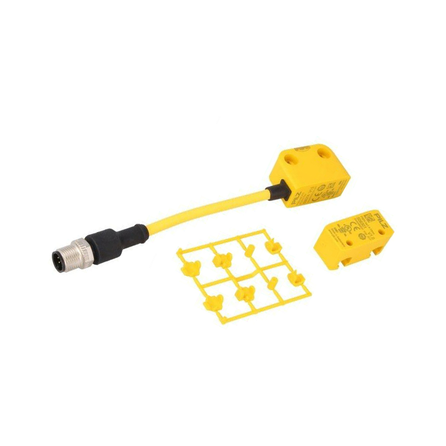
Page 7: Safety Switch Psen Ma1.4P-59
If the actuator is within the response range (safety gate closed), the safety contacts and the auxiliary contact on the safety switch will be closed and the LED will light. Operate the PSEN ma1.4p-59 in conjunction with the following components: Actuator PSEN ma1.4-10mm (see... -
Page 8: Block Diagram
Block diagram Safety switch Actuator Magnet Operating distances (mm) omin Legend Assured operating distance Min. operating distance omin Assured release distance The offset-independent values for the switching distances are included in the Technical details [ 18]. Operating Manual PSEN ma1.4p-59 1003594-EN-06... -
Page 9: Lateral And Vertical Offset
– On evaluation devices with AC supply voltage: Overall cable resistance ≥ 25 Ohms per channel – For details of how to perform the test for shorts across the contacts, please refer to the operating manual for the relevant evaluation device. Operating Manual PSEN ma1.4p-59 1003594-EN-06... -
Page 10: Pin Assignment
PNOZmulti units – may not be used for safety circuits Requirements and connection to evaluation devices For use of PSEN ma1.4p-59 in accordance with DIN EN 60947-5-3 an evaluation device must be connected. Connect the PSEN ma1.4p-59 either with a certified Pilz evaluation device... - Page 11 [ of PSEN ma1.4p-59 – Always comply with the max. switching current safety contacts of PSEN ma1.4p-59. Outputs at the evaluation device must only be switched on again when both reed con- tacts at the safety switch have been opened and closed (partial operation lock)
- Page 12 PSEN ma1.4p-59 PSENmag Evaluation device Input circuit Input circuit Fig.: Dual-channel connection PSEN ma1.4p-59 to the input circuits of an evaluation device Examples for connection to Pilz evaluation devices: PSENmag PNOZ s3 White Yellow Pink Green Operating Manual PSEN ma1.4p-59...
- Page 13 Actuator in the response range Safety contacts and auxili- ary contact Closed lights Open PSENmag PSENmag 24 V 24 V Connecting the auxiliary contact to an eval- Connecting the auxiliary contact to a PLC uation device Operating Manual PSEN ma1.4p-59 | 13 1003594-EN-06...
-
Page 14: Installation
The fastening of safety switch and actuator has to be sufficiently stable to ensure the proper operation of the safety switch and the actuator. The distance between two safety switches must be maintained (see Technical details [ 18]). Operating Manual PSEN ma1.4p-59 | 14 1003594-EN-06... -
Page 15: Installation Type 1
9. Close unused mounting holes using seal (2) (see Diagram [ 16]). 10. Close mounting holes on the sensing face using seal (3) (see Diagram [ 16]). 11. Installation of sensor and actuator is now complete. Operating Manual PSEN ma1.4p-59 | 15 1003594-EN-06... - Page 16 PSEN ma1.4p-59 INFORMATION Seals (1), (2), (3) meet the requirements of UL 94 V0, seal (4) does not meet UL requirements. Operating Manual PSEN ma1.4p-59 | 16 1003594-EN-06...
-
Page 17: Installation Type 2
6. Close mounting holes on the sensing face using seal (3) (see Diagram [ 17]). 7. Installation of sensor and actuator is now complete. INFORMATION Seals (1), (2), (3) meet the requirements of UL 94 V0, seal (4) does not meet UL requirements. Operating Manual PSEN ma1.4p-59 | 17 1003594-EN-06... -
Page 18: Adjustment
Coding level in accordance with EN ISO 14119 Design in accordance with EN ISO 14119 Classification in accordance with EN 60947-5-3 PDDB Electrical data Supply voltage Voltage 24 V Kind Voltage tolerance -20 %/+20 % Max. switching frequency 1 Hz Operating Manual PSEN ma1.4p-59 | 18 1003594-EN-06... - Page 19 Repetition accuracy switching distances Mechanical data Actuator 1 PSEN ma1.4-10mm Typ. Hysteresis 3,5 mm Min. distance between safety switches 50 mm Sensor flush installation in accordance with EN 60947-5-2 Yes, follow installation guidelines Operating Manual PSEN ma1.4p-59 | 19 1003594-EN-06...
-
Page 20: Status Of The Applied Standards
Technical details [ EN 60947-5-3:2005 (classification in accordance with EN 60947-5-3:2013, see Technical details [ 18]) ISO 14119:2013 For undated standards that are not listed here, the latest editions valid on 2015-09 shall ap- ply. Operating Manual PSEN ma1.4p-59 | 20 1003594-EN-06... -
Page 21: Safety Characteristic Data
PSEN cable M8-8sf Extension cable Straight, M8, 8-pin, 0.5 m 533 155 M8-8sm plug/socket PSEN cable M8-8sf Extension cable Straight, M8, 8-pin, 533 156 M8-8sm plug/socket PSEN cable M8-8sf Extension cable Straight, M8, 8-pin, 533 157 M8-8sm plug/socket Operating Manual PSEN ma1.4p-59 | 21 1003594-EN-06... -
Page 22: Ec Declaration Of Conformity
European Parliament and of the Council. The complete EC Declaration of Conformity is available on the Internet at www.pilz.com/downloads. Authorised representative: Norbert Fröhlich, Pilz GmbH & Co. KG, Felix-Wankel-Str. 2, 73760 Ostfildern, Germany Operating Manual PSEN ma1.4p-59... - Page 23 We are represented internationally. Please refer to our homepage www.pilz.com for further details or contact our headquarters. Headquarters: Pilz GmbH & Co. KG, Felix-Wankel-Straße 2, 73760 Ostfildern, Germany Telephone: +49 711 3409-0, Telefax: +49 711 3409-133, E-Mail: info@pilz.com, Internet: www.pilz.com...
Need help?
Do you have a question about the PSEN ma1.4p-59 and is the answer not in the manual?
Questions and answers