Advertisement
Quick Links
22 130-3FR-02
PSEN ma1.4n-50
PSEN ma1.4n-50
22 130-3FR-02
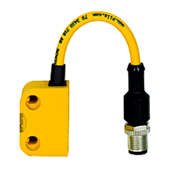
Sicherheitsschalter PSEN ma1.4n-50
Der Sicherheitsschalter erfüllt Forderungen der
833339787
EN 60204-1.
Der Sicherheitsschalter erfüllt EN 60947-5-3
nur zusammen mit den Betätigern PSEN
ma1.4-03mm, PSEN ma1.4-10mm und hierfür
zugelassenen Auswertegeräten.
Schließen Sie den Sicherheitsschalter nur an
Auswertegeräte an, die im Abschnitt "An-
schlüsse" aufgeführt sind.
Zu ihrer Sicherheit
Installieren und nehmen Sie das Gerät nur
547263243
dann in Betrieb, wenn Sie diese Betriebsan-
leitung gelesen und verstanden haben und
Sie mit den geltenden Vorschriften über Ar-
beitssicherheit und Unfallverhütung vertraut
sind.
Beachten Sie die VDE- sowie die örtlichen
Vorschriften, insbesondere hinsichtlich
Schutzmaßnahmen
Durch Öffnen des Gehäuses oder eigen-
mächtige Umbauten erlischt jegliche Ge-
währleistung.
Entfernen Sie die Schutzkappe erst unmittel-
777809547
bar vor Anschluss des Geräts.
Gerätemerkmale
Zum Sicherheitsschalter gehören die Betäti-
510482059
ger PSEN ma1.4-03mm, PSEN ma1.4-
10mm
Sicherheitsschalter mit M12/5-pol. Stecker
1184741515
510237579
2 Sicherheitskontakte (Schließer)
Betätiger PSEN ma1.4-03mm, PSEN
1266751243
ma1.4-10mm:
– Gesicherter Schaltabstand: 3,0 mm, 10,0
mm
– Gesicherter Ausschaltabstand: 12 mm, 22
mm
510316939
eckige Bauform
Wirkweise magnetisch
510321547
510477451
Schaltspannung 24 V DC
Blockschaltbild
Safety switch PSEN ma1.4n-50
The safety switch meets the requirements of
EN 60204-1.
The safety switch only complies with
EN 60947-5-3 in conjunction with the actuators
PSEN ma1.4-03mm, PSEN ma1.4-10mm and
its approved evaluation devices.
The safety switch should only be connected to
the evaluation devices listed under "Connec-
tions".
For your safety
Only install and commission the unit if you
have read and understood these operating
instructions and are familiar with the applica-
ble regulations for health and safety at work
and accident prevention.
Ensure VDE and local regulations are met,
especially those relating to safety.
Any guarantee is rendered invalid if the hous-
ing is opened or unauthorised modifications
are carried out.
Do not remove the protective cap until you
are just about to connect the unit.
Unit features
The actuators PSEN ma1.4-03mm, PSEN
ma1.4-10mm belong to the safety switch
Safety switch with M12/5-pin connector
2 safety contacts (N/O)
Actuator PSEN ma1.4-03mm, PSEN ma1.4-
10mm:
– Assured operating distance: 3,0 mm, 10,0
mm
– Assured release distance: 12 mm, 22 mm
Square design
Works magnetically
Switching voltage 24 VDC
Block diagram
- 1 -
Capteur de sécurité PSEN ma1.4n-50
Le capteur de sécurité satisfait aux exigences
de l'EN 60204-1.
Le capteur de sécurité est conforme à la norme
EN 60947-5-3 uniquement lorsqu'il est utilisé
avec l'actionneur PSEN ma1.4-03mm, PSEN
ma1.4-10mm et les unités de contrôle spécia-
lement homologuées à cet effet.
Ne raccordez le capteur de sécurité qu'aux uni-
tés de contrôle indiquées dans le chapitre
« Raccordements ».
Pour votre sécurité
Vous n'installerez l'appareil et ne le mettrez
en service qu'après avoir lu et compris le
présent manuel d'utilisation et vous être fa-
miliarisé avec les prescriptions en vigueur
sur la sécurité du travail et la prévention des
accidents.
Respectez les normes locales ou VDE, parti-
culièrement en ce qui concerne la sécurité.
L'ouverture de l'appareil ou sa modification
annule automatiquement la garantie.
Veuillez retirer le cache de protection avant
de raccorder l'appareil.
Caractéristiques de l'appareil
Les actionneurs PSEN ma1.4-03mm, PSEN
ma1.4-10mm sont associés au capteur de
sécurité.
Capteur de sécurité avec connecteur M12 à
5 broches
2 contacts de sécurité (contacts à fermeture)
ActionneurPSEN ma1.4-03mm, PSEN
ma1.4-10mm :
– Distance de commutation de sécurité : 3,0
mm, 10,0 mm
– Distance de déclenchement de sécurité :
12 mm, 22 mm
architecture rectangulaire
actionnement magnétique
tension commutée 24 V DC
Schéma de principe
Advertisement

Subscribe to Our Youtube Channel
Related Manuals for Pilz PSEN ma1.4n-50


Summary of Contents for Pilz PSEN ma1.4n-50
- Page 1 PSEN ma1.4n-50 22 130-3FR-02 PSEN ma1.4n-50 Sicherheitsschalter PSEN ma1.4n-50 Safety switch PSEN ma1.4n-50 Capteur de sécurité PSEN ma1.4n-50 833339787 Der Sicherheitsschalter erfüllt Forderungen der The safety switch meets the requirements of Le capteur de sécurité satisfait aux exigences EN 60204-1.
- Page 2 Schaltabstände Operating distances Distances de commutation Legende Légende : Seitenversatz : Lateral offset : Décalage latéral 1267446539 : Höhenversatz : Vertical offset : Décalage en hauteur : Schaltzustände (y-Achse) in Abhängigkeit : Switch statuses (y-axis) dependent on the : Etats de commutation (axe y) en fonction des Schaltabstands (x-Achse) operating distance (x-axis) de la distance de commutation (axe x)
- Page 3 PIN/ Adernfarbe (Pilz Kabel)/ Blockschaltbild/ Function/ Broche Cable colour (Cable Pilz)/ Terminal designation/ Foncion Couleur du fil (fil de Pilz) Désignation des bornes Eingang Kanal 1/ braun/brown/marron Input, channel 1/ Canal d'entrée 1 Ausgang Kanal 1/ weiß/white/blanc Output, channel 1/ Canal de sortie 1 nicht anschließen/...
- Page 4 Anschluss an Auswertegeräte Connection to evaluation devices Raccordement aux unités de contrôle Anschluss an PNOZ X, PNOZsigma, PNO- Connection to PNOZ X, PNOZsigma, Raccordement aux PNOZ X, PNOZsigma, Zelog PNOZelog PNOZelog PNOZ PSENma 24 V PNOZ PSENma PNOZ PSENma Anschluss an PNOZmulti Connection to PNOZmulti Raccordement au PNOZmulti PSENma...
- Page 5 Montage Installation Installation 1095033099 Berücksichtigen Sie bei der Montage die An- When installing make sure you comply with Veuillez tenir compte lors du montage des forderungen der DIN EN 1088 the requirements of DIN EN 1088 exigences de la normes DIN EN 1088. Montieren Sie Sicherheitsschalter und Betä- The safety switch and actuator should be in- Montez le capteur de sécurité...
- Page 6 Montage Variante 1 Installation type 1 Montage du modèle 1 1086268427 1. Gewinde (M4) in gewünschter Position 1. Cut the thread (M4) in the required posi- 1. Couper le filetage (M4) dans la position schneiden. tion. souhaitée. 2. Sensor mit einer Schraube fixieren. 2.
- Page 7 - 7 -...
- Page 8 Montage Variante 2 Installation type 2 Montage du modèle 2 Montieren Sie den Sensor wie bei Montage Va- Install the sensor as shown for installation type Montez le capteur de la même manière que 1086273035 riante 1 pour le modèle 1 1.
- Page 9 Abmessungen in mm Dimensions in mm Dimensions en mm 1 2 7 2 1 5 0 0 2 7 Technische Daten Technical details Caractéristiques techniques Elektrische Daten Electrical data Données électriques Schaltspannung Switching voltage Tension de commutation 24 V Innenwiderstand Internal resistance Résistance interne 10 Ohm...
- Page 10 Bevollmächtigter: Norbert Fröhlich, Pilz GmbH Authorised representative: Norbert Fröhlich, Représentant : Norbert Fröhlich, Pilz GmbH & & Co. KG, Felix-Wankel-Str. 2, 73760 Ostfil- Pilz GmbH & Co. KG, Felix-Wankel-Str. 2, Co. KG, Felix-Wankel-Str. 2, 73760 Ostfildern,...
Need help?
Do you have a question about the PSEN ma1.4n-50 and is the answer not in the manual?
Questions and answers