Table of Contents
Advertisement
Quick Links
Advertisement
Table of Contents

Subscribe to Our Youtube Channel
Related Manuals for Benning CM 2-1


Summary of Contents for Benning CM 2-1
- Page 1 Operating manual Translation of the German original version...
- Page 2 General non-discrimination Benning is aware of the importance of language with regard to the equality of men and women, and endeavours to take this into account at all times. To improve readability, we have refrained from consistently using differentiating formulations.
-
Page 3: Table Of Contents
Connecting the safety measuring lines ................ 27 Voltage or frequency measurement .................. 28 Current or frequency measurement .................. 30 Resistance measurement .................... 31 Continuity testing......................... 32 Capacitance measurement .................... 32 Diode testing ........................ 33 Voltage indicator ......................... 33 5.9.1 Non-contact phase testing .................... 34 5191 / 07/2021 en BENNING CM 2-1... - Page 4 External conductor or phase testing.................. 35 Maintenance ............................. 36 Maintenance schedule ...................... 36 Making the device free of voltage .................. 36 Cleaning the device...................... 37 Replacing the batteries ....................... 38 Calibrating the device...................... 38 Technical data............................ 39 Disposal and environmental protection .................... 40 Index ................................. 41 BENNING CM 2-1 5191 / 07/2021 en...
- Page 5 Figure 3 BENNING TA 2 ..........................Figure 4 BENNING TA 3 ..........................Figure 5 Ø 4 mm measuring lines with 2 mm measuring probe ..............Figure 6 BENNING CM 2‑1 device structure ..................... Figure 7 Rotary switch ..........................Figure 8 Digital display..........................Figure 9 “MODE” function ..........................
- Page 6 Resistance ranges (Ω) ......................... Table 11 Continuity test ..........................Table 12 Diode test............................. Table 13 Capacitance ranges (μF) ......................Table 14 Frequency ranges (Hz) ........................ Table 15 Maintenance schedule ......................... Table 16 Technical data ..........................BENNING CM 2-1 5191 / 07/2021 en...
-
Page 7: Introduction
1.1 General notes Introduction The TRUE RMS digital current clamp multimeter BENNING CM 2‑1 described here (in the following only referred to as “device”) is intended for testing in circuits with a nominal voltage up to a maximum of 600 V‑AC or 600 V‑DC. The device enables you to perform the following tests and measurements: •... -
Page 8: History
Information in this operating manual can be changed at any time without prior notice. Benning is not obligated to make amendments to this operating manual or to keep it up to date. -
Page 9: Service & Support
Phone: +49 2871 93-555 Fax: +49 2871 93‑6555 E-Mail: helpdesk@benning.de Internet: www.benning.de Returns management Easily and conveniently use the BENNING returns portal for a quick and smooth returns processing: https://www.benning.de/service-de/retourenabwicklung.html Phone: +49 2871 93-554 E-Mail: returns@benning.de Return address BENNING Elektrotechnik und Elektronik GmbH & Co. KG Retourenmanagement Robert-Bosch-Str. -
Page 10: Safety
The device has been built and tested in compliance with the following standards and has left the factory in perfectly safe condition. • IEC / DIN EN 61010-1 (VDE 0411‑1) • IEC / DIN EN 61010-2‑032 (VDE 0411‑2‑032) • IEC / DIN EN 61010-2-033 (VDE 0411‑2‑033) • IEC / DIN EN 61010-031 (VDE 0411‑031) BENNING CM 2-1 5191 / 07/2021 en... -
Page 11: Symbols Used
(AC) alternating voltage or alternating current Earth (voltage to earth) Table 2: Symbols on the device Symbols used in the operating manual Symbol Meaning General warning Warning of electric voltage! Table 3: Symbols used in the operating manual 5191 / 07/2021 en BENNING CM 2-1... -
Page 12: Intended Use
– Use of components, accessories, spare or replacement parts that have not been released and approved for the respective application by Benning – Non-observance, manipulation, changes or misuse of the operating manual or the instructions and notes contained therein –... - Page 13 • The device does not work properly in compliance with regulations (e. g. errors during measurements). • The device shows recognisable consequences of prolonged storage under inadmissible conditions. • The device shows recognisable consequences of extraordinary stress due to transport. 5191 / 07/2021 en BENNING CM 2-1...
-
Page 14: Special Types Of Risks
Even low voltages from 30 V‑AC and 60 V‑DC on can be dangerous to human life! • Please observe relevant regulations on occupational safety and health. • If necessary, use appropriate protective equipment. BENNING CM 2-1 5191 / 07/2021 en... -
Page 15: Scope Of Delivery
• Flexible AC current transformer BENNING CFlex 1 (item no.: 044068) AC range: 30 A / 300 A / 3 000 A Figure 1: BENNING CFlex 1 • Set of safety measuring lines BENNING TA 1 (item no.: 044124) Ø 4 mm alligator clips, 2‑piece, red / black, professional version, CAT III 1 000 V, 36 A Figure 2: BENNING TA 1 5191 / 07/2021 en... -
Page 16: Figure 3: Benning Ta 2
Scope of delivery 2.5 Special types of risks • Set of safety measuring lines BENNING TA 2 (item no.: 044125) Set of Ø 4 mm measuring lines, 6‑piece, red / black, professional version, consisting of: – Measuring lines (silicone) (CAT III 1 000 V) – Test probes (4 mm measuring probe, CAT II 1 000 V) –... -
Page 17: Device Description
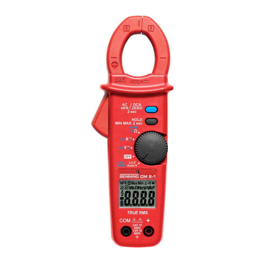
Device description 4.1 Device structure Device description Device structure Figure 6: BENNING CM 2‑1 device structure 1 Measuring clamp (for clamping the 2 “AC HFR / DCA ZERO” key conductor) 3 “HOLD / MIN MAX” key 4 Rotary switch 5 Digital display 6 “+” jack 7 COM jack... -
Page 18: Figure 7 Rotary Switch
1 Current or frequency measurement 2 Resistance, capacitance measurement, continuity or diode testing 3 Setting of the rotary switch 4 Voltage measurement or voltage indicator 5 Device switched off 6 Voltage or frequency measurement BENNING CM 2-1 5191 / 07/2021 en... -
Page 19: Figure 8 Digital Display
By means of a light sensor, the display illumination switches on automatically in dark lighting conditions. Figure 8: Digital display 1 Display of functions and units 2 Display range 3 Battery status 4 Polarity 5 Dangerous contact voltage 5191 / 07/2021 en BENNING CM 2-1... -
Page 20: Functions
The limiting frequency (-3 dB) of the filter is fg = 800 Hz. When reaching the limiting frequency fg, the displayed value is lower by a factor of 0.707 than the actual value without filter. Without low-pass filter With low-pass filter Table 4: Low-pass filter BENNING CM 2-1 5191 / 07/2021 en... -
Page 21: Hold / Min Max" Key
“OFF” position of the rotary switch. • “AC HFR / DCA ZERO” key: Enables or disables the light sensor for automatic display illumination (display “ON” or “OFF”) • “HOLD / MIN MAX” key: Shows all symbols of the digital display 5191 / 07/2021 en BENNING CM 2-1... -
Page 22: Measuring Ranges
• Additional error for AC current or voltage measurements: – Frequency range 15 ... 60 Hz: ±4 % with regard to the specified measuring accuracy – Frequency range >60 Hz: Not specified • Limiting frequency fg (-3 dB): 800 Hz BENNING CM 2-1 5191 / 07/2021 en... -
Page 23: Voltage Ranges
• Input resistance: 10 MΩ Voltage ranges (LoZ, AutoV) Overload protection: 600 V‑AC / V‑DC Measuring range Resolution Measuring accuracy 600 V 1 V ±(2.0 % + 2 digits) Table 7: Voltage ranges (LoZ, AutoV) • Frequency range: 15 Hz … 1 kHz • Input resistance: <4 kΩ 5191 / 07/2021 en BENNING CM 2-1... -
Page 24: Current Ranges
Overload protection: 600 V‑AC / V‑DC Measuring range Resolution Measuring accuracy 400 Ω 0.1 Ω ±(1.0 % + 5 digits) Table 11: Continuity test • The integrated buzzer sounds at a resistance lower than 20 … 200 Ω. • Buzzer response time: <500 μs BENNING CM 2-1 5191 / 07/2021 en... -
Page 25: Diode Test
5 kHz 0.001 kHz 50 kHz 0.01 Hz Table 14: Frequency ranges (Hz) • Minimum sensitivity: – V-AC range 1 Hz … 10 kHz: >6 V – V-AC range 10 … 50 kHz: >20 V – A‑AC range 1 Hz … 10 kHz: >6 A • Minimum frequency: 1 Hz 5191 / 07/2021 en BENNING CM 2-1... -
Page 26: Operation
• Use the device only in electric circuits of overvoltage category III with a conductor for a maximum of 600 V or of overvoltage category IV with a conductor for a maximum of 300 V to earth. BENNING CM 2-1 5191 / 07/2021 en... -
Page 27: Connecting The Safety Measuring Lines
2. Connect the red safety measuring line to the “+” jack of the device. 3. Measurements or tests in circuits of overvoltage category III or IV: Attach the protective caps to the contact tips of the safety measuring lines. 5191 / 07/2021 en BENNING CM 2-1... -
Page 28: Voltage Or Frequency Measurement
5.3 Voltage or frequency measurement Voltage or frequency measurement Requirements • Please observe the requirements for measuring [} page 26]. • Approved safety measuring lines • Voltage ranges [} page 23] and frequency ranges [} page 25] Figure 10: AC voltage or frequency measurement BENNING CM 2-1 5191 / 07/2021 en... -
Page 29: Figure 11 Dc Voltage Measurement
3 kΩ in order to suppress inductive and capacitive voltages (reactive voltages). 2. Connect the safety measuring lines to the device [} page 27]. 3. Bring the safety measuring lines into contact with the measuring points and read the measured value on the digital display. 5191 / 07/2021 en BENNING CM 2-1... -
Page 30: Current Or Frequency Measurement
The “Δ” symbol is shown on the digital display. 4. Operate the opening lever and clamp the single-wire live conductor centrally with the measuring clamp. 5. Read the measured value on the digital display. BENNING CM 2-1 5191 / 07/2021 en... -
Page 31: Resistance Measurement
The “Resistance measurement” function is set automatically (“Ω” is displayed, “ ” is hidden). 2. Connect the safety measuring lines to the device [} page 27]. 3. Bring the safety measuring lines into contact with the measuring points and read the measured value on the digital display. 5191 / 07/2021 en BENNING CM 2-1... -
Page 32: Continuity Testing
3. Press the “AC HFR / DCA ZERO” key to set the desired “Capacitance measurement” function (“n” symbol). 4. Bring the safety measuring lines into contact with the discharged capacitor – observing correct polarity – and read the measured value on the digital display. BENNING CM 2-1 5191 / 07/2021 en... -
Page 33: Diode Testing
• Please observe that a dangerous contact voltage might be applied even if it is not indicated by a visual or acoustic signal. • Do not use the “Voltage indicator” function to test for the absence of voltage. 5191 / 07/2021 en BENNING CM 2-1... -
Page 34: Non-Contact Phase Testing
Practical tip Interruptions (cable breaks) in exposed cables – e. g. in cable reels, chains of light, etc. – can be traced from the feeding point (phase) to the point of interruption. Functional range: ≥230 V BENNING CM 2-1 5191 / 07/2021 en... -
Page 35: External Conductor Or Phase Testing
4. Bring the safety measuring lines into contact with the measuring point (system part). If the symbols “ ” and “EF” are flashing on the digital display, the phase of an earthed alternating voltage is applied to this measuring point. 5191 / 07/2021 en BENNING CM 2-1... -
Page 36: Maintenance
Procedure 1. Remove the device from the measuring point. 2. Disconnect the safety measuring lines from the device. 3. Set the rotary switch of the device to switch position “OFF”. BENNING CM 2-1 5191 / 07/2021 en... -
Page 37: Cleaning The Device
3. In case of electrolyte contamination or white deposits in the area of the battery or the battery compartment, clean the batteries and these areas by means of a clean and dry cloth. Replace the batteries, if necessary [} page 38]. 5191 / 07/2021 en BENNING CM 2-1... -
Page 38: Replacing The Batteries
6. Place the battery compartment cover back onto the device and tighten the screw. Calibrating the device Benning guarantees compliance with this technical and accuracy specifications stated in this operating manual for the first 12 months after the delivery date. To maintain accuracy of the measuring results, make sure that the device is recalibrated in annual intervals by the BENNING Service [} page 9] . -
Page 39: Technical Data
80 % RH (0 … 30 °C), 75 % RH (30 … 40 °C), 45 % RH (40 … 50 °C), non-condensing Storage (remove the batteries from the device) Ambient temperature -20 … 60 °C (do not permanently expose the device to sunlight) Max. relative air humidity 80 % RH Table 16: Technical data 5191 / 07/2021 en BENNING CM 2-1... -
Page 40: Disposal And Environmental Protection
Disposal and environmental protection 6.5 Calibrating the device Disposal and environmental protection At the end of product life, dispose of the unserviceable device and the batteries via appropriate collecting facilities provided in your community. BENNING CM 2-1 5191 / 07/2021 en... -
Page 41: Index
23 Holder of rights 2 Accessories 15 Intended use 12 Basic knowledge 7 Battery Replacing 38 BENNING CM 2-1 7 AC HFR / DCA ZERO 20 HOLD / MIN MAX 21 Calibrating 38 Capacitance measurement 32 Low-pass filter 20 Capacitance ranges 25... - Page 42 Technical data 39 Technical support 9 Test Requirements 26 Trademarks 8 Voltage indicator 34, 35 Practical tip 34 Voltage measurement 29 Voltage ranges (LoZ, AutoV) 23 Voltage-free 36 Warning system 10 Warranty 12 BENNING CM 2-1 5191 / 07/2021 en...
- Page 43 5191 / 07/2021 en BENNING CM 2-1...
- Page 44 BENNING Elektrotechnik und Elektronik GmbH & Co. KG Münsterstraße 135 - 137 D - 46397 Bocholt Phone: +49 2871 93-0 Fax: +49 2871 93-429 Internet: www.benning.de E-Mail: duspol@benning.de BENNING CM 2-1 5191 / 07/2021 en...
Need help?
Do you have a question about the CM 2-1 and is the answer not in the manual?
Questions and answers