Advertisement
Quick Links
Decora Wired
Keypad
Installation Guide
Supported model
C4-KCB-XX
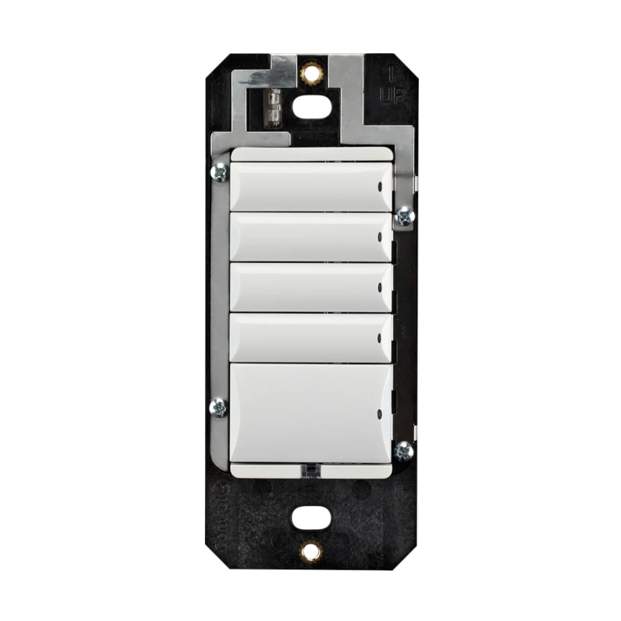
Decora® Wired Keypad
Introduction
The Control4® Decora Wired Keypad is intended for use in a Control4 system. It
installs in a standard US wallbox. Communication to the Control4 system is via RS-
485 protocol and wiring. For RS-485 wiring topologies, refer to the Keypad Bus
ctrl4.co/buswiring
Wiring Guide (
Box contents
•
Decora® Wired Keypad
•
Keycap Button Kit
•
Pluggable Terminal Block
•
Warranty card
Specifications
Model number
Power requirements
Power consumption
Operational temperature
Humidity
Storage
Control communications
Weight
Shipping weight
More help
For the latest version of this guide and to view additional materials, open the URL
below or scan the QR code. Your device must be able to view PDFs.
MOST RECENT VERSION
ctrl4.co/dec-wrd-ig
).
C4-KCB-XX
48VDC
Maximum 48V DC 1.2W
Minimum 48V DC 0.7W
Environmental
0 to 40 ˚C (32 to 104 ˚F)
5% to 95% non-condensing
-20 to 70 ˚C (-4 to 158 ˚F)
Miscellaneous
RS-485
0.045 kg (0.1 lb.)
0.14 kg (0.3 lb.)
BUS WIRING GUIDE
ctrl4.co/buswiring
Warnings and considerations
Important: Using this product in a manner other than outlined in
this document voids your warranty. Further, Control4 is not liable
for any damage incurred with the misuse of this product. See
"Troubleshooting."
Important: Do not use a power screwdriver to install this device. If you
do, you may overtighten the screws and strip them. Also, overtightening
the screws may interfere with proper button operation.
Important: This is an electronic device with intricate components.
Handle and install with care!
Caution! Do not exceed the number of keypads per power supply as
indicated in the Keypad Bus Wiring Guide. Exceeding the maximum
number of keypads will result in overheating the wires and/or failed
devices.
Installation instructions
Caution! When wiring the keypad, make sure that either:
The Bus Power Supply is not powered on.
•
- OR -
•
The pluggable connector is disconnected from the Bus Power
Supply.
1
Prepare the cable for termination by stripping the outer sheath and
individual wires, and then wire into the pluggable terminal block.
2
Wire the keypads as shown below.
Figure 1. Keypad wiring
KeyPad
V+
D+
D-
GND
Tip: If you are using a Control4 push-on (screwless) faceplate in a
multi-gang installation, attach the black faceplate subplate to all of
the devices that will be installed into the wallbox before attaching the
devices to the wallbox. This will help ensure that all devices are properly
aligned and on the same plane after installation.
3
Fit the wires back into the wallbox.
4 Align the keypad to the wallbox (the model number label should be at the
bottom), then fasten it with the included screws.
Important: Tighten the screws until the back side of the yoke plate is
even with the wall surface, but no further. Overtightening can warp the
keypad and cause it to malfunction.
5
Install the top actuator bar, bottom sensor bar, and buttons following the
instructions in the Keypad Buttons Installation Guide (
6
Install the Control4 faceplate following the instructions in the Faceplate
Installation Guide or attach a standard Decora-style or square faceplate.
7
Ensure that the Bus Power Supply is installed correctly and powered on. For
instructions, see the Bus Power Supply, 48V Installation Guide
ctrl4.co/bps48
(
).
KeyPad
V+
D+
D-
GND
ctrl4.co/butn
).
Advertisement

Related Manuals for Control 4 Decora C4-KCB Series


Summary of Contents for Control 4 Decora C4-KCB Series
- Page 1 Warnings and considerations Important: Using this product in a manner other than outlined in this document voids your warranty. Further, Control4 is not liable for any damage incurred with the misuse of this product. See “Troubleshooting.” Important: Do not use a power screwdriver to install this device. If you Decora Wired do, you may overtighten the screws and strip them.
- Page 2 Wiring diagrams ctrl4.co/buswiring For bus wiring details, refer to the Keypad Bus Wiring Guide ( Operation and configuration On initial power up, all status LEDs on the keypad will illuminate green, indicating that the device has power. Until the keypad has been configured into a Control4 system, it will not control any loads.
Need help?
Do you have a question about the Decora C4-KCB Series and is the answer not in the manual?
Questions and answers