Advertisement
Quick Links
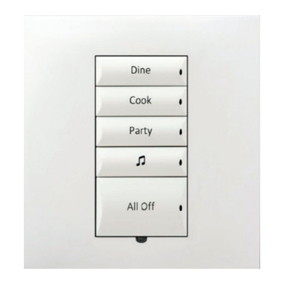
Square Configurable
Wireless Keypad
Installation Guide
Supported model
•
C4-SKC Square Wireless Configurable Keypad
Introduction
The Control4® Square Wireless Configurable Keypad is intended for use in a
Control4 system. It installs in a standard UK or EU wall box using typical wiring
standards and communicates to the Control4 system using a wireless connection.
Box contents
•
Configurable Keypad
•
Square Configurable Wireless Keypad Installation Guide (this document)
•
Keypad Button Installation Guide
•
Warranty card
Specifications
The specifications are described below.
Model number
C4-SKC
Power requirements
120VAC-277VAC +/-10% 50/60 Hz 36-48VDC
This device requires a neutral AC connection.
Power consumption
120V: 350mW
240V: 480mW
277V: 540mW
36VDC: 430mW
Environmental
Operational temperature
0˚C ~ 40˚C (32˚F ~ 104˚F)
Humidity
5% to 95% non-condensing
Storage
-20˚C ~ 70˚C (-4˚F ~ 158˚F)
Miscellaneous
Control communications
ZigBee, IEEE 802.15.4, 2.4 GHz, 15-channel spread
spectrum radio
Weight
0.05 kg (0.12 lb)
Shipping weight
0.08 kg (0.18 lb)
Warnings and considerations
Warning! Turn OFF electrical power before installing or servicing this
product. Improper use or installation can cause SERIOUS INJURY,
DEATH or LOSS/DAMAGE OF PROPERTY.
Attention ! Coupez l'alimentation électrique avant d'installer ou de
réparer ce produit. Une mauvaise installation ou utilisation peut
entraîner des blessures graves, décès ou perte / dommages à la
propriété.
Warning! This device must be protected by a circuit breaker (20A max).
Attention ! Cet appareil doit être protégé par un disjoncteur (20A max.)
Important: When installing the keypad in a round wall box, a Trim
Ring (sold separately) must be installed between the keypad and the
wall box. Trim Rings are available in both single-gang and dual-gang
versions.
Important: This device must be installed by a licensed electrician in
accordance with all national and local electrical codes.
Important: If you are unsure about any part of these instructions,
consult a qualified electrician.
Important: Use this device only with copper or copper-clad wire. Do not
use aluminum wiring. This product has not been approved for use with
aluminum wiring.
Important: Using this product in a manner other than outlined in
this document voids your warranty. Further, Control4 is NOT liable
for any damage incurred with the misuse of this product. See
"Troubleshooting."
Important: Do NOT use a power screwdriver to install this device. If you
do, you may overtighten the screws and strip them. Also, overtightening
the screws may interfere with proper button operation.
Important: This is an electronic device with intricate components.
Handle and install with care!
Installation instructions
1 Ensure that the location and intended use meet the following criteria:
•
When replacing a traditional 3-way switch, refer to the "Two-Location"
sample wiring configurations provided in the appropriate load control
device installation guide.
•
Install in accordance with all national and local electrical codes.
•
The range and performance of the wireless control system is highly
dependent on the following: (1) distance between devices; (2) layout
of the home; (3) walls separating devices; and (4) electrical equipment
located near devices.
2 Turn off the mains electrical power at the consumer unit. To ensure the wires
do not have power running to them, use an inductive voltage detector.
Note: The wall box wiring shown in this document is an example. Your
wire colors and functions may differ.
3 If the keypad is to be installed in a round wall box, attach the Trim Ring to
the wall box following the instructions in the Trim Ring Installation Guide
ctrl4.co/trimring
(
).
4 Prepare each wire. Wire insulation should be stripped back 7mm from the
wire end.
5 Identify and connect the keypad wires to the wall box wires using the
terminal block as shown in Figure 1 below.
Figure 1. Keypad wiring
Line
L
N
Neutral
6 Fit the wires back into the wall box. Bend the wires in a zigzag pattern so
that they easily fold into the wall box.
7 Align the keypad to the wall box or Trim Ring, making sure the arrows
point up, then fasten it with screws. Tighten the screws until the back side
of the yoke plate is even with the wall surface or Trim Ring, but no further.
Overtightening can warp the configurable keypad and cause mechanical
malfunction.
8 Install the buttons as described in the Keypad Button Installation Guide
(
ctrl4.co/butn
).
9 Install the Control4 Faceplate following the instructions in the Faceplate
Installation Guide (
ctrl4.co/faceplate
).
10 Turn ON mains electrical power at the consumer unit.
Operation and configuration
On initial power up, all status LEDs on the keypad will illuminate green indicating
that the device has power. Until the keypad has been configured into a Control4
system, it will not control any loads. To set up this keypad for use with a Control4
system, refer to the Composer Pro User Guide (
ctrl4.co/cpro-ug
).
Button tap sequences
The button tap sequences are defined in the table below. Button tap sequences
that require a single button should use the top-most button installed on the
keypad. Button tap sequences requiring two buttons should use the top-most and
bottom-most buttons installed on the keypad.
Function
Button sequence
Identify
4
ZigBee channel
7
Reboot
15
Factory reset
9-4-9
Leave mesh and reset
13-4-13
Troubleshooting
If the LEDs do not light up indicating that the keypad is receiving power:
•
Ensure circuit breaker is not turned OFF or tripped.
•
Check for proper wiring (see "Installation Instructions" above).
•
For help on the installation or operation of this product, email or call the
Control4 Technical Support Center. Please provide your exact model number.
Contact
support@control4.com
or see the web site www.control4.com.
Care and cleaning
•
Clean surface of the keypad with a soft damp cloth as needed.
•
Do NOT paint the keypad or its wall plate.
•
Do NOT use any chemical cleaners to clean the keypad.
Additional resources
The following resources are available for additional support:
•
Control4 Knowledgebase and forums
•
Control4 Technical Support
•
Control4 website:
www.control4.com
•
Composer documentation in online help or PDF format available on the
Dealer Portal under Support (
ctrl4.co/docs
).
Regulatory and safety information
To review regulatory information for your particular Control4 products, see the
information located on the Control4 website at:
ctrl4.co/reg
.
Warranty
Visit
www.control4.com/warranty
for details.
More help
For the latest version of this document, open this URL or scan the QR code on a
device that can view PDFs.
MOST RECENT VERSION
ctrl4.co/sq-wirelesskp-intl
control4.com | 888.400.4070
Copyright ©2015, Control4 Corporation. All rights reserved. Control4, the Control4 logo,
the 4-ball logo, 4Store, 4Sight, Control My Home, Everyday Easy, and Mockupancy are
registered trademarks or trademarks of Control4 Corporation in the United States and/
or other countries. All other names and brands may be claimed as the property of their
respective owners. All specifications subject to change without notice.
200-00419-B [BETA]
B
b
2015-04-13 MS
Advertisement

Related Manuals for Control 4 C4-SKC


Summary of Contents for Control 4 C4-SKC
- Page 1 Important: This is an electronic device with intricate components. Handle and install with care! More help • C4-SKC Square Wireless Configurable Keypad Button tap sequences For the latest version of this document, open this URL or scan the QR code on a Installation instructions The button tap sequences are defined in the table below.
- Page 2 Regulatory Compliance & Safety Information for Contol4 Model C4-SKC-XX Electrical Safety Advisory Sécurité électrique consultatif Important Safety Information Informations de sécurité importantes Read the safety instructions before using this product. Lisez les consignes de sécurité avant d'utiliser ce produit. 1. Read these instructions.
- Page 3 fournie pour votre sécurité. Si la fiche fournie ne s'adapte pas à votre prise, consultez un électricien pour le remplacement de la prise obsolète. 10. Protect the power cord from being walked on or pinched particularly at plugs, convenience receptacles, and the point where they exit from the apparatus. 10.
- Page 4 16. Pour couper entièrement l'alimentation appareil de l'alimentation secteur, éteignez le disjoncteur. Pour rétablir le courant, mettez le disjoncteur après les consignes de sécurité et des lignes directrices. 17. This product relies on the buildings installation for short-circuit (overcurrent) protection. Ensure that the protective device is rated not greater than: 20A.
- Page 5 Warning!: To reduce the risk of electrical shock, do not expose this apparatus to rain or moisture AVERTISSEMENT! Pour réduire le risque de choc électrique, n'exposez pas cet appareil à la pluie ou à l'humidité. Save these instructions Conservez ces instructions Compliance of this equipment is confirmed by the following label that is placed on the equipment: Conformité...
- Page 6 être déterminé en mettant l'équipement hors et sous tension, l'utilisateur est encouragé à essayer de corriger l'interférence par une ou plusieurs des mesures suivantes: • Réorienter ou déplacer l'antenne de réception. • Augmenter la distance entre l'équipement et le récepteur. •...
- Page 7 RF Radiation Exposure Statement This equipment complies with the FCC/IC radiation exposure limits set fourth for portable transmitting devices operation in an uncontrolled environment. End users must follow the specific operating instructions to satisfy RF exposure compliance. • The equipment should only be used or installed at locations where there is normally greater than a 20cm separation between the antenna and all persons.
- Page 8 Square Wireless Configurable Keypad Brand: Contol4 Model(s): C4-SKC-XX Product Standard(s) to which Conformity of the Council Directive(s) is declared: EMC - 2014/30/EU “Electromagnetic Compatibility (EMC) Directive”: (Emissions) EN 55022:2010, (Immunity) EN 301 489-1 V1.9.2 (2011-09), EN 301 489-17 V2.2.1 (2012-09) Safety –...
- Page 9 Marque: Contol4 Modèle (s): C4-SKC-XX Produit standard (s) dont la conformité de la directive du Conseil (s) est déclarée: EMC - 2014/30 / "compatibilité électromagnétique (CEM)" UE: (Émissions) EN 55022: 2010, (immunité) EN 301 489-1 v1.9.2 (2011-09), EN 301 489-17 V2.2.1 (2012-09)
- Page 10 Platz Drahtlose Konfigurierbare Tastatur Marke: Contol4 Modell (e): C4-SKC-XX Produkt-Norm (en), um die Konformität der Richtlinie (n) deklariert ist: EMC - 2014/30 / EG "Elektromagnetische Verträglichkeit (EMV) Die Richtlinie": (Emissionen) EN 55022: 2010, (Immunität) EN 301 489-1 V1.9.2 (2011-09), EN 301 489-17 V2.2.1 (2012-09)
- Page 11 Marca: Contol4 Modello (s): C4-SKC-XX Prodotto standard (s) a cui conformità della direttiva del Consiglio (s) è dichiarato: EMC - 2014/30 / UE "Compatibilità elettromagnetica (EMC)": (Emissioni) EN 55022: 2010, (immunità) EN 301 489-1 v1.9.2 (2011-09), EN 301 489-17 V2.2.1 (2012-09) Sicurezza - 2006/95 / CE "Direttiva bassa tensione (LVD)":...
- Page 12 Marca: Contol4 Modelo (s): C4-SKC-XX Producto estándar (s) a la que la conformidad de la Directiva del Consejo (s) se declara: EMC - 2014/30 / UE "Directiva de compatibilidad electromagnética (EMC)": (Emisiones) EN 55022: 2010, (inmunidad) EN 301 489-1 v1.9.2 (2011-09), EN 301 489-17 V2.2.1 (2012-09)
- Page 13 Marca: Contol4 Modelo (s): C4-SKC-XX Padrão do produto (s) a que Conformidade da Directiva do Conselho (s) é declarado: EMC - 2014/30 / UE "Compatibilidade Electromagnética (EMC)": (Emissões) EN 55022: 2010, (Imunidade) EN 301 489-1 v1.9.2 (2011-09), EN 301 489-17 V2.2.1 (2012-09)
- Page 14 Recycling Control4 understands that a commitment to the environment is essential for a health life and sustainable growth for future generations. We are committed to supporting the environmental standards, laws, and directives that have been put in place by various communities and countries that deal with concerns for the environment.
Need help?
Do you have a question about the C4-SKC and is the answer not in the manual?
Questions and answers