Advertisement
Quick Links
Supported Model
•
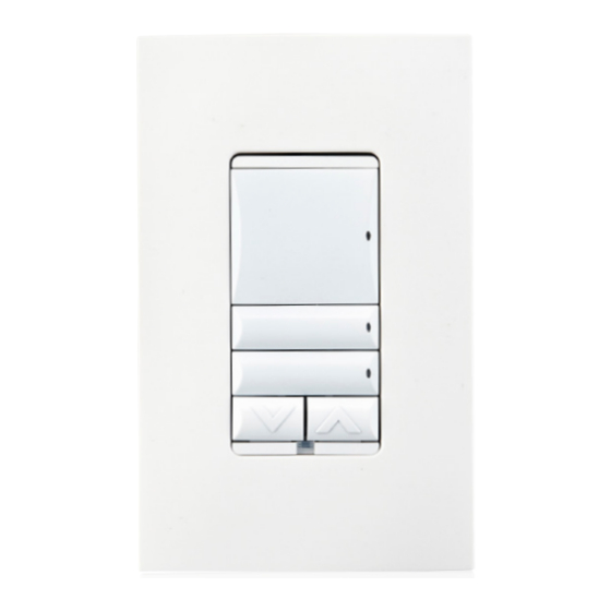
C4-KCB-XX Wired Configurable Keypad
Introduction
The Control4® Configurable Decora Wired Keypad is intended for use in a Control4
system. It installs in a standard US wallbox. Communication to the Control4 system
is via RS-485 protocol and wiring. For RS-485 wiring topologies, refer to the
document Keypad Bus Wiring Recommendations.
Box Contents
•
Configurable Decora Wired Keypad
•
Keycap Button Kit
•
Pluggable Terminal Block
•
Warranty Card
Specifications
The specifications are described below.
Model Number
Power Requirements
Power Consumption
Operational Temperature
Humidity
Storage
Control Communications
Weight
Shipping Weight
Configurable
Decora
®
Wired
Keypad
Installation Guide
C4-KCB-XX
48VDC
Maximum 24VDC 0.9W
Minimum 24VDC 0.5W
Maximum 48VDC 1.2W
Minimum 48VDC 0.7W
Environmental
32˚F - 104˚F (0˚C - 40˚C)
5% to 95% non-condensing
-4˚F - 158˚F (-20˚C - 70˚C)
Miscellaneous
RS-485
0.1 lb. (0.045 kg)
0.3 lb. (0.14 kg)
™
Warnings and Considerations
IMPORTANT!
Using this product in a manner other than outlined in this
document voids your warranty. Further, Control4 is NOT liable for any
damage incurred with the misuse of this product. See "Troubleshooting."
IMPORTANT!
Do NOT use a power screwdriver to install this device. If you
do, you may overtighten the screws and strip them. Also, overtightening
the screws may interfere with proper button operation.
IMPORTANT!
This is an electronic device with intricate components.
Handle and install with care!
CAUTION!
Do not exceed the number of keypads per power supply as
indicated in Figures 2, 3, and 4 on the next page. Exceeding the maximum
number of keypads will result in overheating the wires and/or failed
devices.
Installation Instructions
CAUTION!
When wiring the keypad, make sure that either:
The Bus Power Supply is not powered on.
•
- OR -
•
The pluggable connector is disconnected from the Bus Power Supply.
1
Prepare the CAT5 cable for termination by stripping the outer sheath and
individual wires, then wire into the pluggable terminal block by using the
recommended wiring shown below.
Terminal
GND
D+
D-
V+
2
Wire the keypads as shown below.
Figure 1.
KeyPad
V+
D+
TIP: If you are using a Control4 push-on (screwless) faceplate in a
multi-gang installation, attach the black faceplate subplate to all of
the devices that will be installed into the wallbox before attaching
the devices to the wallbox. This will help ensure that all devices are
properly aligned and on the same plane after installation.
3
Fit the wires back into the wallbox.
4
Align the keypad to the wallbox (the model number label should be at the
bottom), then fasten it with the included screws.
IMPORTANT!
Tighten the screws until the back side of the yoke plate
is even with the wall surface, but no further. Overtightening can warp
the keypad and cause it to malfunction.
5
Install the top actuator bar, bottom sensor bar, and buttons following the
instructions in the Keypad Buttons Installation Guide.
6
Install the Control4 faceplate following the instructions in the Faceplate
Installation Guide or attach a standard decora-style faceplate.
Wire
Color
Orange White + Green
3 × Wire
White + Brown White
1 × Wire
Blue
1 × Wire
Blue White
3 × Wire
Orange + Green + Brown
KeyPad
D-
GND
V+
D+
D-
GND
Advertisement

Related Manuals for Control 4 C4-KCB-XX


Summary of Contents for Control 4 C4-KCB-XX
- Page 1 Do not exceed the number of keypads per power supply as • C4-KCB-XX Wired Configurable Keypad indicated in Figures 2, 3, and 4 on the next page. Exceeding the maximum number of keypads will result in overheating the wires and/or failed devices.
-
Page 2: Troubleshooting
Ensure that the Bus Power Supply is installed correctly and powered on. For Regulatory/Safety Information instructions, see the Bus Power Supply Installation Guide. To review Regulatory information for your particular Control4 products, see the information located on the Control4 website at: Operation and Configuration http://www.control4.com/regulatory/. - Page 3 ™ Figure 2. Single Chain - Gateway and Power Supply at the Beginning of the Chain To Keypads Max 40 Keypads Max 1000ft Bus Power Supply Bus Ethernet Gateway Figure 3. Two Chains - Gateway and Power Supply Centrally Located Between Chains To Keypads Max 25 To Keypads Max 25 Keypads...
- Page 4 Copyright ©2013 Control4. . All rights reserved. Control4, the Control4 logo, the Control4 iQ logo and the Control4 certified logo are registered trademarks or trademarks of Control4 Corporation in the United States and/or other countries. All other names and brands may be claimed as the property of their respective owners Pricing and specifications are subject to change without notice...
Need help?
Do you have a question about the C4-KCB-XX and is the answer not in the manual?
Questions and answers