Table of Contents
Advertisement
Quick Links
Configurable Keypad
Installation Guide
Supported model
•
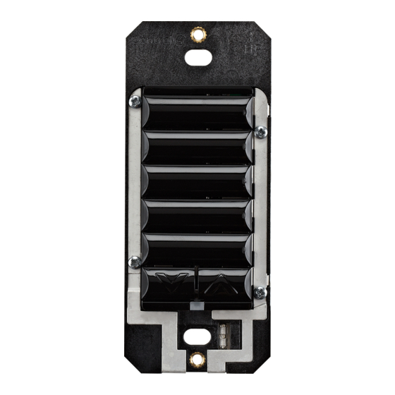
C4-KC120277 Wireless Configurable Keypad
Introduction
The Control4® Configurable Keypad is intended for use in a Control4 system. It
installs in a standard wallbox using typical wiring standards and communicates to
the Control4 system using a wireless connection.
Box contents
•
Configurable Keypad
•
Keycap Button Kit
•
Wire nuts
•
Warranty card
•
Configurable Keypad Installation Guide (this document)
•
Keypad Button Installation Guide
Specifications
The specifications are described below.
Model number
Power requirements
Power consumption
Operational temperature
Humidity
Storage
Control communications
Wallbox volume
Weight
Shipping weight
Copyright ©2023, Snap One, LLC. All rights reserved. Snap One and its respective logos are
registered trademarks or trademarks of Wirepath Home Systems, LLC, dba "Control4" and/
or dba "SnapAV" in the United States and/or other countries. Other names and brands may be
claimed as the property of their respective owners. All specifications subject to change without
notice.
™
C4-KC120277-xx
120-277V AC +/-10% 50/60 Hz
36-48V DC
This device requires a neutral AC connection.
120V: 350mW
277V: 540mW
36V DC: 430mW
Environmental
0 to 40 ˚C (32 to 104 ˚F)
5% to 95% non-condensing
-20 to 70 ˚C (-4 to 158 ˚F)
Miscellaneous
Zigbee, IEEE 802.15.4, 2.4 GHz, 15-channel
spread spectrum radio
4.75 cubic inches
0.05 kg (0.12 lb.)
0.08 kg (0.18 lb.)
200-00309-H 20230913MK
Warnings and considerations
WARNING!
Turn OFF electrical power before installing or servicing this
product. Improper use or installation can cause SERIOUS INJURY, DEATH
or LOSS/DAMAGE OF PROPERTY.
ATTENTION!
Coupez l'alimentation électrique avant d'installer ou de
réparer ce produit. Une mauvaise installation ou utilisation peut entraîner
des blessures graves, décès ou perte / dommages à la propriété.
WARNING!
This device must be protected by a circuit breaker (20A max).
ATTENTION!
Cet appareil doit être protégé par un disjoncteur (20A max.)
WARNING!
Ground this device in accordance with the National Electric
Code (NEC) requirements. DO NOT rely solely upon the yoke plate's
contact with a metal wallbox for adequate grounding. Use the device's
ground wire to make a secure connection to the safety ground of the
electrical system.
ATTENTION!
Cet appareil doit être en conformité avec le Code national de
l'électricité (NEC). Ne comptez pas uniquement au contact de la plaque
avant avec un boîtier mural métallique pour la mise à la terre adéquate.
Utilisez cet appareil à la terre de l'appareil pour établir une connexion
sécurisée au système électrique.
IMPORTANT!
This device must be installed by a licensed electrician in
accordance with all national and local electrical codes.
IMPORTANT!
If you are unsure about any part of these instructions,
consult a qualified electrician.
IMPORTANT!
Use this device only with copper or copper-clad wire. Do
not use aluminum wiring. This product has not been approved for use with
aluminum wiring.
IMPORTANT!
Using this product in a manner other than outlined in this
document voids your warranty. Further, Control4 is NOT liable for any
damage incurred with the misuse of this product. See "Troubleshooting."
IMPORTANT!
Do NOT use a power screwdriver to install this device. If you
do, you may overtighten the screws and strip them. Also, overtightening
the screws may interfere with proper button operation.
IMPORTANT!
This is an electronic device with intricate components.
Handle and install with care!
IMPORTANT!
When used in conjunction with an Auxiliary Keypad
(C4-KA-xx), the wire connecting the Auxiliary Keypad to the Configurable
Keypad must not exceed 45 m (150 ft.) at 120V AC, and 30 m (100 ft.) at
277V AC.
Installation instructions
1
Ensure that the location and intended use meet the following criteria:
•
When replacing a traditional 3-way switch, refer to the "Two-Location"
sample wiring configurations provided in the appropriate load control
device installation guide.
•
Install in accordance with all national and local electrical codes.
•
The range and performance of the wireless control system is highly
dependent on the following: (1) distance between devices; (2) layout
of the home; (3) walls separating devices; and (4) electrical equipment
located near devices.
2
Turn off the local electrical power by either switching off the circuit breaker or
removing the fuse from the fuse box. To ensure the wires do NOT have power
running to them, use an inductive voltage detector.
Advertisement
Table of Contents

Related Manuals for Control 4 C4-KC120277


Summary of Contents for Control 4 C4-KC120277
- Page 1 WARNING! Ground this device in accordance with the National Electric • C4-KC120277 Wireless Configurable Keypad Code (NEC) requirements. DO NOT rely solely upon the yoke plate’s contact with a metal wallbox for adequate grounding. Use the device’s ground wire to make a secure connection to the safety ground of the Introduction electrical system.
- Page 2 ™ Align the keypad to the wallbox (the model # label should be at the bottom) NOTE: The wallbox wiring shown in this document is an example. Your and fasten it with screws. Tighten the screws until the back side of the yoke wire colors and functions may differ.
- Page 3 ™ Figure 4. Low-voltage bus power wiring diagram Configurable Wired Keypad Wired (C4-KC120277-XX) Keypad Keypad Black/Brown (Line In) White/Blue (Neutral) D– D– Green/Yellow (Ground) To more D– Wired Keypads V+ D+ D– GND V+ D+ D– GND Bus Ethernet Gateway...
Need help?
Do you have a question about the C4-KC120277 and is the answer not in the manual?
Questions and answers