Table of Contents
Advertisement
Quick Links
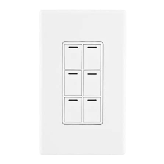
Wireless 2, 3, and 6-Button
Keypad Installation Guide
Supported Models and Requirements
•
C4-KP2-Z Wireless 2-Button Keypad
•
C4-KP3-Z Wireless 3-Button Keypad
•
C4-KP6-Z Wireless 6-Button Keypad
Specifications
This Control4
multi-button Keypad is intended for use in a Control4 system. It installs
®
in a standard wall box using typical wiring standards and communicates to the Control4
system using a wireless connection. The specifications are described next.
Power:
120 VAC +/-10% 50/60 Hz
400 mW
This device requires a neutral AC
connection.
Supported Load Types:
Not Applicable. This device does not directly control
a load.
Communications:
IEEE 802.15.4, 2.4 GHz, 15-channel, spread
spectrum radio
Warnings and Considerations
WARNING! Install in accordance with all national and local electrical codes.
WARNING! Improper use or installation can cause SERIOUS INJURY,
DEATH or LOSS/DAMAGE OF PROPERTY.
WARNING! If you are unsure about any part of these instructions, consult a
qualified electrician.
WARNING! To reduce the risk of SERIOUS INJURY or DEATH, turn OFF
local electrical power before installing this product, and before installing,
removing, or replacing keycaps.
IMPORTANT! Using this product in a manner other than outlined in this
document voids your warranty. Further, Control4 is NOT liable for any
damage incurred with the misuse of this product. See "Limited 2-Year
Warranty."
IMPORTANT! Do NOT use a power screwdriver to install this device. If you
do, you may overtighten the screws and strip them.
IMPORTANT! This is an electronic device with intricate components. Handle
and install with care!
Installation Instructions
1.
Ensure that the location and intended use meet the following criteria:
•
When replacing a traditional 3-way switch, refer to the "Two-Location" sample
wiring configurations provided in the following documents:
Wireless Dimmer Installation Guide
Wireless Switch Installation Guide
•
Install in accordance with all national and local electrical codes.
•
The required wall box size is specified by the NEC (National Electrical Code).
The internal wall box volume occupied by this multi-button keypad is 5.0 cubic
inches.
•
The range and performance of the wireless control system is highly dependent
on the following: (1) distance between devices; (2) layout of the home; (3) walls
separating devices; and (4) electrical equipment located near devices.
•
If you are planning to use engraved keycaps for 3-Button and 6-Button Key-
pads, DO NOT continue until you have read the "Replace Keycaps" section.
•
If installing a multi-button keypad in a multi-gang installation, DO NOT continue
until you have read the "Multi-Gang Installations" section.
WARNING! To reduce the risk of SERIOUS INJURY or
DEATH, turn OFF local electrical power before installing this
product.
2. Turn off the local electrical power by either switching off the circuit breaker or remov-
ing the fuse from the fuse box. To ensure the wires do NOT have power running to
them, use an inductive voltage detector.
WARNING! As with any electrical device, improper use or installation can
cause SERIOUS INJURY or DEATH. It is important that you understand the
particular wiring configuration of your installation before proceeding. Note: The
wall box wiring shown in this document is an example. Your wire colors and
functions may differ. If you are not sure which wires are the Hot, Neutral, and
Ground wires, have a trained electrician do the installation.
3. Prepare each wire. Wire insulation should be
stripped back 5/8 of an inch from the wire end
(as shown).
WARNING! WARNING! Ground the Wireless Keypad in accordance with the
National Electric Code (NEC) requirements. Although the Keypad's aluminum
yoke plate and green ground wire are directly bonded together inside the
keypad, DO NOT rely solely upon the yoke plate's contact with a metal wall
box for adequate grounding. Use the Keypad's ground wire to make a secure
connection to the safety ground of the electrical system.
IMPORTANT! Not grounding this product according to the preceding may
result in an installation less immune to damage caused by electrical
disturbances, such as lightning, and void the warranty.
4. If you need to "Replace Keycaps" or do "Multi-Gang Installations," refer to those
sections before continuing.
5. Identify and connect the multi-button
Keypad wires to the wall box wires using
the wire nuts.
Note: Wall box wires can differ depend-
ing upon how the box was wired by your
electrician.
To wire the multi-button Keypad, connect
and cap the wires with a wire nut as
indicated in the following table.
Multi-Button Keypad Wires
(2,3, or 6-Button)
White (neutral)
White (neutral)
Green (ground)
Green (ground)
Black (hot)
Black (hot)
Wires in Wall Box
Advertisement
Table of Contents

Subscribe to Our Youtube Channel
Related Manuals for Control 4 C4-KP2-Z


Summary of Contents for Control 4 C4-KP2-Z
-
Page 1: Specifications
• The range and performance of the wireless control system is highly dependent on the following: (1) distance between devices; (2) layout of the home; (3) walls separating devices; and (4) electrical equipment located near devices. • If you are planning to use engraved keycaps for 3-Button and 6-Button Key- pads, DO NOT continue until you have read the “Replace Keycaps” section. • If installing a multi-button keypad in a multi-gang installation, DO NOT continue until you have read the “Multi-Gang Installations” section. WARNING! To reduce the risk of SERIOUS INJURY or DEATH, turn OFF local electrical power before installing this product. Supported Models and Requirements 2. Turn off the local electrical power by either switching off the circuit breaker or remov- ing the fuse from the fuse box. To ensure the wires do NOT have power running to • C4-KP2-Z Wireless 2-Button Keypad them, use an inductive voltage detector. • C4-KP3-Z Wireless 3-Button Keypad • C4-KP6-Z Wireless 6-Button Keypad WARNING! As with any electrical device, improper use or installation can cause SERIOUS INJURY or DEATH. It is important that you understand the Specifications particular wiring configuration of your installation before proceeding. Note: The wall box wiring shown in this document is an example. Your wire colors and functions may differ. If you are not sure which wires are the Hot, Neutral, and This Control4 multi-button Keypad is intended for use in a Control4 system. It installs ® Ground wires, have a trained electrician do the installation. in a standard wall box using typical wiring standards and communicates to the Control4 system using a wireless connection. The specifications are described next. -
Page 2: Troubleshooting
Operation and Configuration Fit the wires back into the wall box. Bend the wires in a zigzag pattern so that they easily fold into the wall box. On initial power up, the unit will flash the Red/Green/Blue (RGB) LEDs which can be programmed with different colors for different states or color preferences. To set up this Keypad for use with a Control4 system, refer to the Composer Pro User Guide. Troubleshooting If one or more Light Emitting Diodes (LEDs) are not lit: If you are using the Control4 push-on (screwless) wall plate that shipped with your multi-button Keypad: • Ensure circuit breaker is not turned OFF or tripped. Align the multi-button Keypad to the wall box and fasten • Check for proper wiring, such as the example in Step 5. You may also need to contact it with screws. Tighten the screws until the back side of a trained electrician. the metal yoke plate is even with the wall surface, but no • For help on the installation or operation of this product, email or call the Control4 further. Overtightening can warp the multi-button Keypad Technical Support Center. Please provide your exact model number. Contact and cause mechanical malfunction. support@control4.com or see the web site www.control4.com. Care and Cleaning • Do NOT paint the multi-button keypad or its wall plate. With the wall plate’s removal slot facing down, push the wall plate onto the Keypad’s black plastic sub-plate. • Do NOT use any chemical cleaners to clean the multi-button keypad. • Clean surface with a soft damp cloth as needed. 8. - Page 3 Recycling For recycling information, please go to www.control4.com/recycling. Protected under U.S. Patents D519,939 and D518,794 and licensed under U.S. Patents 5,905,442 and 5,982,103 Limited 2-Year Warranty For complete warranty information, including details on consumer legal rights as well as warranty exclusions, visit www.control4.com/warranty. About this Document ©2011 Control4. All rights reserved. Control4, the Control4 logo, the Control4 iQ logo and the Control4 certified logo are registered trademarks or trademarks of Control4 Cor- poration in the United States and/or other countries. All other names and brands may be claimed as the property of their respective owners. Pricing and specifications are subject to change without notice. Part Number: 200-00037 Rev D 2/11/2011...
Need help?
Do you have a question about the C4-KP2-Z and is the answer not in the manual?
Questions and answers