Advertisement
Quick Links
Supported Model
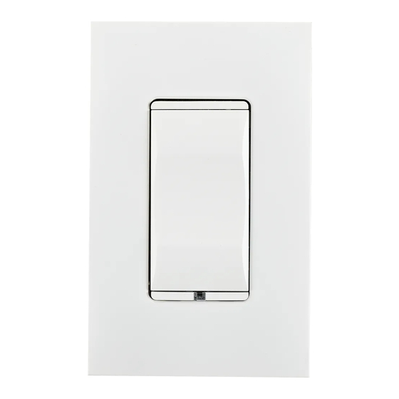
C4-KA Auxiliary Keypad
Introduction
The Control4® Auxiliary Keypad is intended for use in a Control4 system. It installs
in a standard wallbox and connects and communicates with a compatible Control4
dimmer or switch using the traveler wire.
Box Contents
Auxiliary Keypad
Wire Nuts
Warranty Card
Compatible Devices
The Auxiliary Keypad can connect to and control any of the following Control4
devices:
C4-APD120 Adaptive Phase Dimmer
C4-APD240 Adaptive Phase Dimmer
C4-APD277 Adaptive Phase Dimmer
C4-FPD120 Forward Phase Dimmer
C4-KD120 Keypad Dimmer
C4-KD240 Keypad Dimmer
C4-KD277 Keypad Dimmer
C4-SW120277 Switch
C4-SW240 Switch
C4-TV120277 0-10V Dimmer
C4-TV240 0-10V Dimmer
C4-4SF120 Fan Speed Controller
Specifications
The specifications are described below.
Model Number
Power Requirements
Operational Temperature
Humidity
Storage
Wallbox Volume
Weight
Shipping Weight
Auxiliary Keypad
Installation Guide
(this document)
C4-KA-xx
120/240/277 VAC +/-10% 50/60 Hz
Environmental
32˚ F - 104˚ F (0˚ C - 40˚ C)
5% to 95% non-condensing
-4˚ F - 158˚ F (-20˚ C - 70˚ C)
Miscellaneous
4.75 cubic inches
0.07 lb. (0.03 kg)
0.12 lb. (0.05 kg)
™
Warnings and Considerations
WARNING!
Turn OFF electrical power before installing or servicing this
product. Improper use or installation can cause SERIOUS INJURY, DEATH
or LOSS/DAMAGE OF PROPERTY.
ATTENTION!
Coupez l'alimentation électrique avant d'installer ou de
réparer ce produit. Une mauvaise installation ou utilisation peut entraîner
des blessures graves, décès ou perte / dommages à la propriété.
This device must be protected by a circuit breaker (20A max).
WARNING!
ATTENTION!
Cet appareil doit être protégé par un disjoncteur (20A max.)
WARNING!
Ground this device in accordance with the National Electric
Code (NEC) requirements. DO NOT rely solely upon the yoke plate's
contact with a metal wallbox for adequate grounding. Use the device's
ground wire to make a secure connection to the safety ground of the
electrical system.
ATTENTION!
Cet appareil doit être en conformité avec le Code national
de l'électricité (NEC). Ne comptez pas uniquement au contact de la
plaque avant avec un boîtier mural métallique pour la mise à la terre
adéquate. Utilisez cet appareil à la terre de l'appareil pour établir une
connexion sécurisée au système électrique.
IMPORTANT!
This device must be installed by a licensed electrician in
accordance with all national and local electrical codes.
IMPORTANT!
If you are unsure about any part of these instructions,
consult a qualified electrician.
Use this device only with copper or copper-clad wire. Do
IMPORTANT!
not use aluminum wiring. This product has not been approved for use with
aluminum wiring.
Install in accordance with all applicable national and local
IMPORTANT!
electrical codes.
IMPORTANT!
Using this product in a manner other than outlined in this
document voids your warranty. Further, Control4 is NOT liable for any
damage incurred with the misuse of this product. See "Troubleshooting."
IMPORTANT!
Do NOT use a power screwdriver to install this device. If you
do, you may overtighten the screws and strip them. Also, overtightening
the screws may interfere with proper button operation.
IMPORTANT!
This is an electronic device with intricate components.
Handle and install with care!
Installation Instructions
1
Turn off the local electrical power by either switching off the circuit breaker or
removing the fuse from the fuse box. To ensure the wires do NOT have power
running to them, use an inductive voltage detector.
NOTE:
The wallbox wiring shown in this document is an example. Your
wire colors and functions may differ. If you are not sure which wires are
the Hot, Neutral, and Ground wires, have a trained electrician do the
installation.
2
Prepare each wire. Wire insulation should be stripped back 5/8 of an inch
from the wire end (see Figure 1).
Advertisement

Related Manuals for Control 4 C4-KA


Summary of Contents for Control 4 C4-KA
- Page 1 Ground this device in accordance with the National Electric Code (NEC) requirements. DO NOT rely solely upon the yoke plate’s C4-KA Auxiliary Keypad contact with a metal wallbox for adequate grounding. Use the device’s ground wire to make a secure connection to the safety ground of the electrical system.
- Page 2 up. Release the button at the desired level. Figure 1. Strip Wire Insulation When connected to a dimmer, press and hold the bottom button to fade the load down. Release the button at the desired level. Troubleshooting If the Auxiliary Keypad does not control the load that is connected to the associated dimmer, switch, or Fan Speed Controller: Ensure that the circuit breaker is not turned OFF or tripped.
Need help?
Do you have a question about the C4-KA and is the answer not in the manual?
Questions and answers