Table of Contents
Advertisement
Quick Links
Dear Client
Thank you for Purchasing our ETCR2000 Clamp Type Earth
Resistance Tester. Please read the manual in detail prior to first
use, which will help you use the equipment skillfully.
company's products continually, so there may be
slight differences between your purchase equipment
and its instruction manual. You can find the changes
in the appendix. Sorry for the inconvenience. If you have further
questions, welcome to contact with our service department.
may bring voltage, when you plug/draw the test wire or
power outlet, they will cause electric spark. PLEASE
CAUTION RISK OF ELECTRICAL SHOCK!
Company Address:
T4,No. 41, High-tech 2 Road,East Lake High-tech Development Zone,
Wuhan
Sales Hotline: 86-27- 87457960
After Service Hotline: 86-27- 87459656
Fax: 86-27- 87803129
E-mail: qiao@hvtest.cc
Website: www.hvtest.cc
Our aim is to improve and perfect the
The input/output terminals and the test column
1
Advertisement
Table of Contents

Subscribe to Our Youtube Channel
Related Manuals for HVTest ETCR2000


Summary of Contents for HVTest ETCR2000
- Page 1 Dear Client Thank you for Purchasing our ETCR2000 Clamp Type Earth Resistance Tester. Please read the manual in detail prior to first use, which will help you use the equipment skillfully. Our aim is to improve and perfect the company's products continually, so there may be slight differences between your purchase equipment and its instruction manual.
- Page 2 SERIOUS COMMITMENT All products of our company carry one year limited warranty from the date of shipment. If any such product proves defective during this warranty period we will maintain it for free. Meanwhile we implement lifetime service. Except otherwise agreed by contract.
- Page 3 ground pole of the shell must be grounded. To prevent electric shock, the grounding conductor must be connected to the ground. Make sure the product has been grounded correctly before connecting with the input/output port. Pay Attention to the Ratings of All Terminals To prevent the fire hazard or electric shock, please be care of all ratings and labels/marks of this product.
- Page 4 -Security Terms Warning: indicates that death or severe personal injury may result if proper precautions are not taken Caution: indicates that property damage may result if proper precautions are not taken.
-
Page 5: Table Of Contents
Contents I. Attention....................6 II. Brief Introduction................7 III. Specification..................8 1. Model of Series......................8 2. Ranges and Accuracy of Measurement..............9 3. Technical Specifications....................9 IV. Structure of Meter................10 V. Crystal Display..................11 1. LCD Screen.........................11 2. Description of Special Symbols................12 3. -
Page 6: Attention
I. Attention Thank you for purchasing this pincer earth tester from ETCR Electronic. In order to make better use of the product, please be certain: --To read this user manual carefully. --To comply with the operating cautions presented in this manual. ... -
Page 7: Brief Introduction
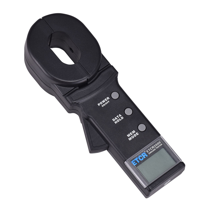
Pincer Earth Tester can measure the integrated value of the grounding body resistance and the grounding lead resistance. ETCR2000 series of Pincer Earth Tester is equipped with a long jaw, as indicated in the figure below. A long jaw is particularly suitable for the occasion of grounding with the flat steel. -
Page 8: Specification
III. Specification 1. Model of Series Note: “√” means available. -
Page 9: Ranges And Accuracy Of Measurement
2. Ranges and Accuracy of Measurement Note: "*" is limited to ETCR2000C. 3. Technical Specifications Power Source: 6VDC (4 ×5# alkaline battery) Working Temperature: -10 ° -55 ° C Relative Humidity: 10%-90% LCD: 4-digital LCD, 47 × 28.5mm width Net Weight (including batteries): 1130g Demension: 275mm long, 85 mm wide, 56mm thick Protection Level: Double insulation Structural Feature: In the jaw way... -
Page 10: Structure Of Meter
External Magnetic Field: <40A/m External Electric Field: <1V/m Measuring Time: 1 second Resistance Measurement Frequency: >1KHz Maximum Resistance Measurement Resolution: 0.001 Ω Resistance Measurement Range: 0.01-1000 Ω *Current Measuring Range: 0.00-30.0A * Measured Current Frequency: 50/60Hz * Storable Measurement Data: 99 Units *Setting Range of Resistance Alarm Critical Value: 1-199 Ω... -
Page 11: Crystal Display
*7. SET Key: function key combinations (Combination with MODE key to achieve: Lock / Release / Storage / Set / Check / Browse / Delete Data) Note: "*" is limited to ETCR2000C. V. Crystal Display 1. LCD Screen (1). Alarming sign (2). -
Page 12: Description Of Special Symbols
2. Description of Special Symbols (1). Symbol of an open jaw: As a jaw is in the open state, the symbol shows. At this point, trigger may be artificially pressed, or the jaws have been seriously polluted, and can no longer continue to measure. (2). - Page 13 (2) ---Measured loop resistance is less than 0.01 Ω (3) ---Measured loop resistance is 5.1 Ω (4) ---Measured loop resistance is 2.1 Ω ---Lock the current measurement value: 2.1 Ω *(5) ---Access to the stored data of Unit No. 26 ---Measured loop resistance is 0.028 Ω...
-
Page 14: Quick Find Table
critical value of alarm setting. --- Access to the stored data unit No. 8 ---Measured resistance is 820 Ω Note: "*" is limited to ETCR2000C. VI.Quick Find Table Function Boot Up / Shutdown / Shutdown Delay POWER HOLD Lock / Release Display * Quit POWER *Resistance measurement / current measurement / Data... - Page 15 CAL5, CAL4:CAL0, OL Ω" , see Figure 2. When "OLΩ" appears, auto inspection is completed, and then automatically enter the resistance measurement model, see figure 3. In the process of auto inspection, DO NOT press the trigger, nor open the jaw, nor clamp any wire. In auto-inspection process, be sure to maintain the natural static state of the Meter;...
-
Page 16: Shutdown
flashes the symbol , as shown in Figure 5. Due to that no-load resistance "OL" has exceeded the alarm critical value of resistance. 2. Shutdown After the Meter is switched on, press POWER key to shut it down. In five minutes after the Meter started up, the LCD screen entered flashing state, and would automatically shut down after the flashing state is sustained for 30 seconds to reduce battery consumption. -
Page 17: Current Measurement
consistent with the normal value on the test ring (5.1 Ω). The normal value on the test ringis the value at a temperature of 20 ° C. It is normal to find the difference of numerical 1 word between the show value and the nominal value, For instance: If the nominal value of test ring is 5.1 Ω, it would be normal showing 5.0 Ω... -
Page 18: Data Lock/Release/Storage
see Figure 7. At this point, press the trigger and open the jaws, clamp the target wire, reading to get the current value. It shows "OL A”, indicating that the measured current value exceeded the upper limit of Meter, see Figure 8. Flash symbol indicates that the measured current value has gone beyond the alarm critical value. -
Page 19: Data Access
MEM symbol would flashs display. *As indicated in Figure 9, lock the measured resistance 0.016Ω, and save it as data unit No.1. *As indicated in Figure 10, lock the measured current 278mA, and save it as data unit No.50.And the memory is full now. *In the access mode, press MODE key to switch to the measurement mode, then the operation can be done to lock and save data. -
Page 20: Setting Of Alarm Critical Value
*7. Setting of Alarm Critical Value Press MODE key enter the measurement mode of resistance or current. After pressing down SET key for 3 sec, you can enter the setting function of alarm critical value. At this point, the highest-digit begins to flash. First set the highest digit as indicated in Figure 13 and Figure 14. -
Page 21: Clear Data
VIII. Measurement Principle 1. Principle of Resistance Measurement The basic principle of ETCR2000 in the measurement of resistance is to measure the loop resistance, as shown in the figure below. The jaw part of the Meter is comprised of voltage coil and current coil. The voltage coil provides excitation signal, and will induce a... -
Page 22: Principle Of Current Measurement
generate on the measured loop. The Meter will measure E & I, and the measured resistance R can be obtained by the following formula. 2. Principle of Current Measurement The basic principle of ETCR2000C in the measurement of current is the same with that of the measurement of resistance, as shown in the figure below. - Page 23 buildings, etc.), They usually pass the overhead ground wire (cable shielding layer) connected to form a grounding system. As the Meter is in the above measurement, its equivalent electric circuit is shown in the figure below: Where: R is the target grounding resistance. is the equivalent resistance of the other entire tower grounding resistances paralleled.
-
Page 24: Limited Point Grounding System
2. Limited Point Grounding System This is also quite common. For example, in some towers, five towers are linked with each other through overhead ground wire; Besides, the grounding of some of the buildings is not an independent grounding grid, but several grounding bodies connected with each other through the wire. -
Page 25: Single-Point Grounding System
3. Single-Point Grounding System From the measuring principle, ETCR2000 series Meter can only measure the loop resistance, and the single-point grounding is not measured. However, users will be able to use a testing line very near to the earth electrode of the grounding system to artificially create a loop for testing. - Page 26 resistance value by connecting the test lines with both ends. So, if the measurement value of the Meter is smaller than the allowable value of the grounding resistance, then the two grounding bodies are qualified for grounding resistance. (2) Three-Point Method As shown in the figure below, in the vicinity of the measured grounding body R find two independent grounding bodies of better grounding state R...
- Page 27 In the above three steps, the reading measured in each step is the value of the two series grounding resistance. In this way, we can easily calculate the value of each grounding resistance: From: We get: ...
Need help?
Do you have a question about the ETCR2000 and is the answer not in the manual?
Questions and answers