Table of Contents
Advertisement
Instructions-Parts
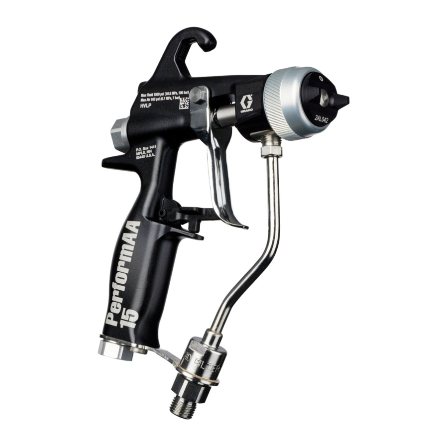
PerformAA™ Spray
Gun
Air assist and airless spray guns for fine finish application of various solventborne and
waterborne paints and coatings. For professional use only.
100 psi (0.7MPa, 7 bar) Maximum Working Air Pressure.
See page 3 for model information including maximum working
fluid pressure.
Important Safety Instructions
Read all warnings and instructions in this
manual before using the equipment.
Save these instructions.
Important Medical Information
Read the medical alert card provided with
the gun. It contains injection injury
treatment information for a doctor. Keep it
with you when operating the equipment.
PerformAA 15
Air Assist
Airless
PerformAA 50
Air Assist
Airless
3A8099A
EN
PerformAA RAC
Air Assist
II 2G Ex h IIB T6 Gb
Advertisement
Table of Contents
Troubleshooting

Related Manuals for Graco PerformAA 15


Summary of Contents for Graco PerformAA 15
- Page 1 Important Safety Instructions Read all warnings and instructions in this manual before using the equipment. Save these instructions. PerformAA 15 Important Medical Information Air Assist Airless Read the medical alert card provided with the gun. It contains injection injury treatment information for a doctor.
-
Page 2: Table Of Contents
Troubleshooting ......25 Graco Standard Warranty ....62 Spray Pattern Troubleshooting . -
Page 3: Models
Models Models ™ PerformAA 15 Air Assist Gun Models Medium-pressure gun includes carbide seat and ball, 100 mesh inline fluid filter, indexing air cap, and choice of AXM or AXF spray tip (unless otherwise noted). Includes Maximum Working Air Cap Part Fluid Model Fluid Pressure... -
Page 4: Performaa ™ Rac Air Assist Gun Models
Models ™ PerformAA RAC Air Assist Gun Models High-pressure gun includes carbide seat/ball and choice of LTX or FFLP RAC SwitchTip. Includes Maximum Working Air Cap Fluid Model Fluid Pressure Air Cap Assembly Swivel psi (MPa, bar) Connector 26B517 5000 (34.5, 345) ®... -
Page 5: Warnings
Warnings Warnings The following are general warnings related to the setup, use, grounding, maintenance, and repair of this equipment. Additional, more specific warnings may be found throughout the body of this manual where applicable. Symbols that appear in the body of the manual refer to these general warnings. When these symbols appear throughout the manual, refer back to these pages for a description of the specific hazard. - Page 6 Warnings WARNING EQUIPMENT MISUSE HAZARD Misuse can cause death or serious injury. • Do not operate the unit when fatigued or under the influence of drugs or alcohol. • Do not exceed the maximum working pressure or temperature rating of the lowest rated system component.
-
Page 7: Spray Gun Overview
Spray Gun Overview Spray Gun Overview The air assist spray gun combines the airless and air spray concepts. Airless and air assist spray: Air assist spray: • Hydraulic force pushes high-pressure fluid through • Air from the air cap further atomizes the fluid and the spray tip orifice. -
Page 8: Component Identification
Compatible with npsm and bsp female swivel connectors. Fan Adjustment Knob Adjusts fan pattern shape (21g) and width. Improves gun Fluid Swivel maneuverability. Included Connector (22) with select models. See Models, page 3. . 2: PerformAA 15 without fluid swivel 3A8099A... -
Page 9: Typical Installation
Fluid Filter Grounding Wire Key: Suction Hose Air Shutoff Valve Fluid Drain Valve Air Line Filter Paint Supply Pail Gun Air Pressure Regulator Air Line Bleed Type Master Air Valve . 3: Typical installation (PerformAA 15 model 26B501 shown) 3A8099A... -
Page 10: Typical Installation Accessories
Typical Installation Typical Installation Accessories Fluid Line Accessories Install the accessories shown in F . 3, using adapters as necessary. • Fluid filter (I): with a 60 or 100 mesh (250 micron) stainless steel element to filter particles from the Air Line Accessories fluid as it leaves the pump. -
Page 11: Setup
Setup Setup Ventilate the Spray Booth Do not operate the gun unless ventilating air flow is above the minimum required value. Provide fresh air ventilation to avoid the buildup of flammable or toxic vapors when spraying, flushing, or cleaning the gun. Interlock the gun fluid supply to prevent operation unless ventilating air flow is above the minimum required value. -
Page 12: Flush Before Using
Setup Flush Before Using 3. Connect the gun fluid supply hose (G) to the fluid inlet fitting (15) or the fluid swivel connector (22). See F . 6. The equipment was tested with lightweight oil, which is left in the fluid passages to protect parts. To avoid NOTE: Purchase a fluid swivel connector (22) contaminating your fluid with oil, flush the equipment separately with Kit 189018. -
Page 13: Spray Tip And Air Cap Setup
6. Rotate the air cap (8a) to the horizontal or vertical spray pattern position. See F . 9. NOTE: PerformAA 15 models can be positioned precisely with an air cap alignment pin (8e). See Alignment Pin Adjustment, page 14. 4. Install the spray tip (7) in the air cap (8a) with the tip locating tab positioned in the air cap slot. -
Page 14: Reverse-A-Clean® (Rac) Setup
Setup Alignment Pin Adjustment 4. Insert the RAC SwitchTip. The air cap alignment pin (8e) is factory-set to the vertical spray pattern position. See F 1. Unscrew the air cap alignment pin (8e) with needle SwitchTip nose pliers. 2. Move the alignment pin (8e) to the desired position. See F . -
Page 15: Operation
Operation Operation Be sure to read and follow the Warnings starting on Optional: Open all fluid drain valves in the system with page 5 and throughout the body of this instruction a waste container ready to catch drainage. manual. 6. Engage the trigger lock (3). See F . -
Page 16: Spray Gun Operation
. 14: Low starting pressure PerformAA 15 and PerformAA 50 Air Assist 3. Trigger the gun to check the atomization; do not Follow the Spray Gun Operation Procedure. adjust the pattern shape yet. - Page 17 Operation 5. Turn the fan adjustment knob (21g) clockwise until 8. Slowly increase the inlet air pressure until the tails completely closed. are completely atomized and pulled into the spray pattern. See F . 20. Too little air No air Correct amount of air pressure...
-
Page 18: Spray Finishing Application
Operation Spray Finishing Application Narrow Pattern Turn the fan adjustment knob (21g) counterclockwise 1. Maintain a distance of approximately 8 to 12 in. (200 (open). See F . 22. to 300 mm) from the object being sprayed. If the pattern is still not narrow enough, then increase 2. -
Page 19: Maintenance
Maintenance Maintenance To reduce the risk of an injury, follow the Pressure Relief Procedure, page 15, whenever you are instructed to relieve the pressure. Daily Gun Care 1. Follow the Pressure Relief Procedure, page 15. . 27: Flush the gun 4. - Page 20 Maintenance NOTE: Always point the gun down during cleaning to prevent solvent entering the gun air passages. Solvent left in gun air passages could result in a poor quality paint finish. 6. Clean the outside of the gun with a soft cloth. .
-
Page 21: Flushing Procedure
Maintenance Flushing Procedure NOTICE Methylene chloride with formic or propionic acid will damage aluminum and nylon components. Do not use to flush or clean the gun. 5. Point the gun down into a grounded metal container. Hold a metal part of the gun firmly to the grounded metal container. -
Page 22: Cleaning Procedure
Maintenance Cleaning Procedure 6. Clean the air cap assembly (8) and spray tip (7) 1. Follow the Pressure Relief Procedure, page 15. 2. Remove the air cap assembly (8) and spray tip (7). 3. Flush the gun with a compatible solvent. See Flushing Procedure, page 21. - Page 23 Maintenance 11. Clean the inline fluid filter (14). a. Unscrew the fluid inlet fitting (15). b. Remove the inline fluid filter (14) from the fluid tube assembly (13). c. Clean or replace. . 38: Clean outside of gun 9. Clean the fluid cartridge (6) if necessary. a.
-
Page 24: Reverse-A-Clean (Rac) Tip Maintenance
Maintenance Reverse-A-Clean (RAC) Tip 4. Trigger the gun into a pail to clear the clog. Maintenance To avoid serious injury from skin injection, do not put your hand in front of the spray tip when removing, installing, or maintaining the air cap assembly. NOTE: Do not soak the RAC tip seat gasket (33a) in solvent for extended periods of time or swelling may occur. -
Page 25: Troubleshooting
Troubleshooting Troubleshooting Spray Pattern Troubleshooting Follow Pressure Relief Procedure, page 15, before checking or repairing the gun. To reduce the risk of a skin injection injury, always follow the Pressure Relief Procedure, page 15, NOTE: Check all possible problems and causes before whenever instructed to relieve the pressure. - Page 26 Troubleshooting Why it is Problem Possible Causes Solutions important • Spray tip partially • Clean or replace tip • Even and Irregular pattern plugged blended finish • Clean or replace air cap • Dirty or plugged air • Even 50% cap holes •...
- Page 27 Troubleshooting Why it is Problem Possible Causes Solutions important • Too much atomization • Decrease air pressure • Air caps are Entrained Air/ Sugary Finish/ designed to Champagne Finish • Test different type of air deliver • Over agitation of paint supply •...
-
Page 28: General Troubleshooting
Troubleshooting General Troubleshooting 1. Follow Pressure Relief Procedure, page 15 before checking or repairing the gun. 2. Check all possible problems and causes before disassembling gun. Problem Cause Solution Fluid leakage from the back of Worn packings or needle shaft. Replace the fluid cartridge. - Page 29 Troubleshooting Problem Cause Solution No fluid output when triggered. Spray tip is plugged. Clean spray tip. See Cleaning Procedure, page 22. Fluid hose is plugged. Follow Pressure Relief Procedure, page 15. Very slowly loosen the hose end coupling to relieve pressure gradually. Loosen the nut or the coupling completely.
-
Page 30: Repair
Repair Repair 5. Lubricate the air cartridge tip and thread the air cartridge assembly (21) into the back of the gun. Torque to 175-185 in-lb (20-21 N•m). See F . 42. Trigger Procedure To avoid injury, follow Pressure Relief Procedure, page 15, before checking or repairing the gun. -
Page 31: Air Cap Assembly Repair Procedure
30. spray tip Lubricate lightly. Lips face the tool. . 45: PerformAA 15 air cap assembly parts and spray tip Assemble the Air Cap . 46: U-cup replacement. 1. Place the washer (8f) onto the front of the air cap (8a). -
Page 32: Air Cartridge Repair
Repair Air Cartridge Repair a. Place the replacement fan valve o-ring (21k) onto the fan valve stem (21f). Thread the fan 1. Follow the Pressure Relief Procedure, page 15. adjustment nut (21e) onto the stem (21f). Lubricate the o-ring (21k). 2. - Page 33 Repair Torque to 175-185 in-lb (20-21 N•m) Lubricate lightly . 47: Air cartridge assembly (for air assist models) Air Valve Replacement 5. Pull the air valve (21a) and spring (21b) from the cartridge enclosure (21d). Replace the air valve (21a) with kit 26B713. 6.
-
Page 34: Fan Tube Replacement
Repair Fan Tube Replacement Fluid Cartridge Replacement Replace the fan tube with kit 26B715. Replace the fluid cartridge (6) entirely with a compatible replacement kit. See Fluid Cartridge Repair Kits, 1. Follow the Pressure Relief Procedure, page 15. page 55. 2. -
Page 35: Fluid Cartridge Repair
Repair Fluid Cartridge Repair Rebuild the fluid cartridge or replace fluid cartridge parts with a compatible repair kit. See Fluid Cartridge Repair Kits, page 55. 1. Follow the Pressure Relief Procedure, page 15. 2. Remove Fluid Cartridge Procedure, page 34, to remove the fluid cartridge assembly (6) from the gun. - Page 36 Repair b. Use a pick to install outer needle assembly c. Thread the diffuser assembly (6a) and needle o-rings (6c). assembly (6b) together. Torque to 45-50 in-lb (5-6 N•m). c. Press the internal o-ring (6c) into the needle assembly (6b). Push the needle forward while d.
- Page 37 Repair Fluid Tube Assembly Replacement 8. Install a new fluid tube assembly (13) into the gun. Use kit 26B711 to replace the fluid tube assembly (13). 9. Install the fluid tube screw (17) with a 3/16 in. hex wrench. Torque to 50-60 in-lb (6-7 N•m). 1.
- Page 38 Repair Fluid Tube Seal Replacement Torque to 175-185 1. Follow the Pressure Relief Procedure, page 15. in-lb (20-21 N•m) Torque to 50-60 in-lb 2. Remove the fluid tube assembly (13). 2 4 5 (6-7 N•m) Torque to 150-160 a. Remove the air inlet fitting (16) with the gun tool 2 4 5 6 in-lb (17-18 N•m) (29).
-
Page 39: Parts
Parts Parts PerformAA 15 Air Assist Gun Models Models 26B500, 26B501, 26B502, 26B503, 26B504, and 26B505. 3A8099A... - Page 40 Parts PerformAA 15 Air Assist Gun Models Models 26B500, 26B501, 26B502, 26B503, 26B721 TRIGGER, GUN (includes 26B504, and 26B505 10 and 11) 15F739 PIN, PIVOT Ref. Part No. Description Qty. 15F740 PIN, PIVOT, NUT 26B711 KIT, FLUID TUBE, filter BODY, gun...
-
Page 41: Performaa 50 Air Assist Gun Models
Parts PerformAA 50 Air Assist Gun Models Models 26B509, 26B510, 26B511, 26B512 26B513, 26B514, 26B515, and 26B516 3A8099A... - Page 42 Parts PerformAA 50 Air Assist Gun Models Models 26B509, 26B510, 26B511, 26B512 26B711 KIT, FLUID TUBE, filter, all 26B513, 26B514, 26B515, and 26B516 models except 26B509, (kit includes 14, 15, and 17) Ref. See Fluid Tube Assembly Part No. Description Qty.
-
Page 43: Performaa Rac Air Assist Gun Models
Parts PerformAA RAC Air Assist Gun Models Models 26B517and 26B518 3A8099A... - Page 44 Parts PerformAA RAC Air Assist Gun Models Models 26B517and 26B518 26B867 FITTING, AIR Part No. Description Qty. 119996 SCREW, CAP, SCKT, LH, 1/4-20X3/8 BODY, gun PLUG, FAN AIR, (purchase 188493 PACKING, U-CUP, GUN kit 26B715: includes 19 and 249423 STOP, TRIGGER (kit includes item 4) 112319 PACKING, O-RING...
-
Page 45: Performaa Airless Gun Models
Parts PerformAA Airless Gun Models Models 26B519 and 26B520 3A8099A... - Page 46 Parts PerformAA Airless Gun Models Models 26B519 and 26B520 205264 FILTER, TIP, see Inline Fluid Ref. Part Description Qty. Filter Kits, page 55 for options 24D437 FITTING, HOSE, filter BODY, gun 26B868 PLUG, AIR, AIRLESS 188493 PACKING, U-CUP, gun 119996 SCREW, CAP, SCKT, LH, 249423 STOP, TRIGGER (kit includes 1/4-20X3/8 item 4)
-
Page 47: Air Cartridge Assembly
Parts Air Cartridge Assembly 26B713: Air Cartridge Assembly Kit with a fan adjustment knob for air assist models 26B717: Fixed Air Cartridge Assembly Kit for RAC and airless models 21g* KNOB, FAN ADJUSTMENT Ref. Part Description Number 21h* GC2082 SCREW, set 26B716 VALVE, ASSY., AIR 21j*... -
Page 48: Fluid Cartridge Assembly
Parts Fluid Cartridge Assembly (internal) 26B700 Fluid Cartridge Kit PerformAA with carbide 26B701 Fluid Cartridge Kit SST with stainless steel ball and seat. ball, plastic seat, and low viscosity spring. Used in models 26B500, 26B501, 26B509, 26B510, Use in model 26B504. Not compatible with PerformAA 26B511, 26B512, 26B513, 26B514,26B515, 26B516, 50 or RAC models. -
Page 49: Fluid Tube Assembly Parts
Parts Fluid Tube Assembly Parts 26B702 Fluid Cartridge Kit: Wood Lacquer and Low Viscosity with carbide ball and seat and low viscosity spring. See Fluid Tube Repair Kits, page 55 for kit numbers. Used in models 26B502, 26B503, and 26B505. Not compatible with PerformAA 50 or RAC models. -
Page 50: Spray Tip Charts
Spray Tip Charts Spray Tip Charts PerformAA 15, PerformAA 50, and PerformAA Airless Spray Tips PerformAA models are compatible with the following spray tips: AXM Fine Finish Spray Tips (AXMxxx): Recommended for high finish quality applications. Use the AXM and GG4 Spray Tip Matrix Table, page 50. - Page 51 *Tips are tested in water. Measured with NO airflow. Air assist will tend to reduce pattern lengths by 1 in. to 2 in. ‡Do not use these tips with PerformAA 15 gun models. †150 mesh tip filter included. ~AXM tips only.
- Page 52 Spray Tip Charts Table 2: AXF Fine Finish Pre-Orifice Spray Tips Matrix Table Maximum Pattern Width at 12 in. (305 mm) *Fluid Output in. (mm) Orifice Size 2 to 4 4 to 6 6 to 8 8 to 10 10 to 12 12 to 14 14 to 16...
-
Page 53: Performaa Rac Switchtips
Spray Tip Charts PerformAA RAC SwitchTips PerformAA RAC models are compatible with the Order desired tip, where xxx = 3-digit spray tip Part No. following RAC spray tips: from the matrix table. Example: Order LTX209 for the LTX RAC Spray tip with a 0.009 in. (0.229 mm) orifice LTX RAC Spray Tips (LTXxxx): Recommended for and a maximum spray pattern of 2 to 4 in. -
Page 54: Air Cap Selection Guide
Air Cap Selection Guide Air Cap Selection Guide Air caps are versatile, and more than one air cap can meet your finishing requirements. Select an air cap based on coating properties, finishing requirements, and operator preference. To reduce the risk of injury, follow the Pressure Relief Procedure, page 15, before removing or installing a tip and/or air cap. -
Page 55: Kits And Accessories
Kits and Accessories Kits and Accessories Kits Inline Fluid Filter Kits 238563 60 Mesh Inline Fluid replacement filters Fluid Cartridge Repair Kits Filters (3 pack) 238561 100 Mesh Inline Fluid replacement filters Carbide Seat Repair Kits Filters (3 pack) 26B707 Diffuser 25N892 150 Mesh Inline Fluid... -
Page 56: Accessories
Spray Pattern Test Sheet (single) 101892 Gun Brush 19C706 Spray Pattern Test Sheet (Pack of 25) 15C161 Ultimate Gun cleaning Kit 249598 Unclogging Needle Kit 15G093 PerformAA 15 Gun Flush Insert 15G346 PerformAA 50 Gun Flush Insert 111265 Gun Lubricant 3A8099A... -
Page 57: Dimensions
Dimensions Dimensions Perform AA 15 Air Assist and Airless Gun Models 26B500, 26B501, 6 in. (252.4 mm) 1.5 in. (38.1 mm) 8.2 in. (208.3 mm) 1/4-18 npsm (m) 1/4-18 npsm 26B502, 26B503, (R1/4-19) 26B505, 26B504, compound 26B519* male thread *dimension E does not apply 3A8099A... - Page 58 Dimensions PerformAA 50 Air Assist and Airless Gun Models 26B510, 26B511, 6.8 in. (172.7 mm) 2.2 in. (55.9 8.2 in. (208.3 mm) 1/4-18 npsm (m) 1/4-18 npsm 26B512, 26B513, (R1/4-19) 26B514, 26B515, compound 26B516, 26B509, male thread 26B520* *dimension E does not apply. 3A8099A...
- Page 59 Dimensions PerformAA RAC Air Assist Gun Models 26B517, 26B518 7.2 in. (182.9 mm) 2.8 in. (71.1 mm) 7.8 in. (198.1 mm) 1/4-18 npsm (m) 1/4-18 npsm (R1/4-19) compound male thread 3A8099A...
-
Page 60: Technical Specifications
Technical Specifications Technical Specifications PerformAA Spray Guns Metric Maximum working fluid pressure PerformAA 15 air assist models 1500 psi 10.5 MPa, 105 bar PerformAA 50 air assist models 5000 psi 34.5 MPa, 345 bar Perform AA RAC air assist models 5000 psi 34.5 MPa, 345 bar... -
Page 61: Air Flow
Air Flow Air Flow General Finishing (GF), Wood Lacquer (WL), and Quick Drying (QD) and High Viscosity (HV)Air Caps Top Coat (TC) Air Caps (283) (283) Air Flow Air Flow (227) (227) SCFM SCFM (SLPM) (SLPM) (170) (170) (113) (113) (57) (57) (0.3) -
Page 62: Graco Standard Warranty
With the exception of any special, extended, or limited warranty published by Graco, Graco will, for a period of twelve months from the date of sale, repair or replace any part of the equipment determined by Graco to be defective.
Need help?
Do you have a question about the PerformAA 15 and is the answer not in the manual?
Questions and answers