Graco Magnum TrueAirless ProX19 Owner's Manual
Hide thumbs
Also See for Magnum TrueAirless ProX19:
- Owner's manual (60 pages) ,
- Kit instructions (2 pages) ,
- Owner's manual (56 pages)
Table of Contents
Advertisement
''
3A9019A EN
Important Safety Instructions
Read all warnings and instructions in this manual, related manuals, and on the
unit, before using the equipment. Be familiar with the controls and the proper
usage of the equipment. Save these instructions.
Magnum Products Operational Videos
http://magnum.graco.com/magop/
For portable spray applications of architectural paints and coatings only.
Not approved for use in explosive atmospheres or hazardous (classified) locations.
888-541-9788
http://magnum.graco.com/magop/
Advertisement
Table of Contents

Related Manuals for Graco Magnum TrueAirless ProX19


Summary of Contents for Graco Magnum TrueAirless ProX19
- Page 1 Be familiar with the controls and the proper usage of the equipment. Save these instructions. Magnum Products Operational Videos http://magnum.graco.com/magop/ For portable spray applications of architectural paints and coatings only. Not approved for use in explosive atmospheres or hazardous (classified) locations.
-
Page 2: Before You Spray
Review Warnings for Important Safety Information Important! Read carefully and practice good safety habits. Related Manuals 312830 SG Spray Guns 3A3172 ProXChange™ Pump Magnum Products Operational Videos http://magnum.graco.com/magop/ Models 3000 psi (207 bar, 20.7 MPa) Maximum Working Pressure Charger Voltage (VAC) Model Cart 25U478... -
Page 3: Table Of Contents
Contents Contents Before You Spray ............. 2 Contents . - Page 4 Graco Standard Warranty ........
-
Page 5: Important Grounding Information
Important Grounding Information Important Grounding Information The following information is intended to help you understand when to use the grounding wire and clamp provided with your sprayer. Please read the information on the material container label to determine if it is oil-based or flammable. Ask for a Safety Data Sheet (SDS) from your supplier. -
Page 6: Warnings
All parts of the spray system, including the pump, hose assembly, spray gun, and objects in and around the spray area shall be properly grounded to protect against static discharge and sparks. Use Graco conductive or grounded high-pressure airless paint sprayer hoses. Follow Grounding Instructions, page 11. - Page 7 Check hoses and parts for signs of damage. Replace any damaged hoses or parts. • This system is capable of producing 3000 psi (207 bar, 20.7 MPa). Use Graco parts or accessories that are rated a minimum of 3000 psi (207 bar, 20.7 MPa).
- Page 8 Warnings WARNING PRESSURIZED ALUMINUM PARTS HAZARD Use of fluids that are incompatible with aluminum in pressurized equipment can cause serious chemical reaction and equipment rupture. Failure to follow this warning can result in death, serious injury, or property damage. • Do not use 1,1,1-trichloroethane, methylene chloride, other halogenated hydrocarbon solvents or fluids containing such solvents.
-
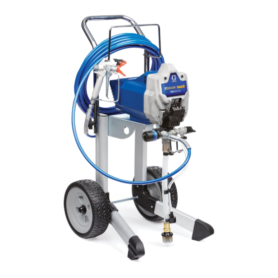
Page 9: Know Your Sprayer
Know Your Sprayer Know Your Sprayer ProX19 Cart Sprayer Airless Hose Power - ON/OFF Switch ™ Pressure Control Knob InstaClean Filter (inside fluid outlet) Prime/Spray Valve Pail Hanger Spray Tip Inlet Screen PushPrime Button Battery Suction Tube Easy Access Door Drain Tube (with diffuser) Pump Removal Tool Airless Spray Gun... -
Page 10: Know Your Controls
Know Your Controls Know Your Controls The ON/OFF power switch controls the main power to your sprayer. The power button is illuminated when ON. The Pressure Control knob increases or decreases the pressure and flow of the paint. The Prime/Spray Valve directs the fluid to either the Drain Tube or the hose and gun. -
Page 11: Grounding Instructions
Grounding Instructions Grounding Instructions (Oil-Based or Flammable Materials) Fluid hoses: Use only electrically conductive hoses with a maximum of 300 ft. (91 m) combined hose length to ensure grounding continuity. Spray gun: Grounded through connection to a The equipment must be grounded to reduce the properly grounded fluid hose and pump. - Page 12 Grounding Instructions Always ground a metal pail: connect a ground wire to the pail. Clamp one end to the pail and the other end to a true earth ground such as a water pipe. ti24584a To maintain ground continuity when sprayer is flushed or pressure is relieved: hold metal part of spray gun firmly to the side of a grounded metal pail then trigger the gun.
-
Page 13: Setup
Setup Setup Assemble Your Sprayer Connect airless hose to airless hose connection (P) on sprayer. Use wrench to tighten securely. To avoid serious injury from skin injection, Connect the other end of the hose to the do not put your hand in front of the Spray gun. -
Page 14: Battery Installation And Removal
Setup Battery Installation and Removal Always start with a fully charged battery. Install battery by aligning the battery Do not splash or immerse battery or pack with the rails inside the sprayer and charger in water. See battery and charger sliding it in until the battery pack is firmly information shipped with the sprayer. -
Page 15: Start Up
Start Up Start Up Pressure Relief Procedure Turn pressure control knob to lowest setting. Follow the Pressure Relief Procedure whenever you see this symbol. Put Drain Tube into a waste pail and turn This equipment stays pressurized until Prime/Spray Valve down to PRIME position to relieve pressure. -
Page 16: Flush Storage Fluid
Start Up Flush Storage Fluid Align setting indicator with the START setting on the pressure control knob. It is important that you flush storage fluid from the sprayer before using it. Make certain ON/OFF switch is OFF. Button is not illuminated when OFF. Separate Drain Tube (smaller) from Suction Tube (larger). -
Page 17: Strain The Paint
Start Up Fill Pump (Prime Pump) 10. Turn the ON/OFF switch to OFF position. Button is not illuminated when OFF. The Prime/Spray Valve directs the fluid to either the Drain Tube or the hose and gun. It is used to prime the sprayer, which means to evacuate the air out of the pump, hose, and gun. -
Page 18: Fill Gun And Hose
Start Up Fill Gun and Hose Release trigger. Engage trigger lock. Rotate Spray Tip to UNCLOG position and ensure the Spray Tip Guard is tight. Hold gun against waste pail. Point gun into waste pail. High-pressure spray is able to inject toxins into the body and cause serious Disengage trigger lock (A). -
Page 19: Refill Paint Pail
Start Up Refill Paint Pail When the paint pail runs low and the gun stops spraying, refill the paint pail and repeat the Fill Pump (Prime Pump) procedure, then the Fill Gun and Hose procedure. You are now ready to spray! NOTE: It is normal for the motor to stop once the sprayer is primed and under pressure. -
Page 20: Spraying
Spraying Spraying Start Turn pressure control knob to START Disengage trigger lock. position. Adjust Pressure Control To select a setting, align symbol on pressure control knob with setting indicator on sprayer. For best spray results with lowest overspray, adjust pressure control to “START” setting. Test the spray pattern on a test area or piece of cardboard. -
Page 21: Spray Techniques
Spraying Spray Techniques Use a piece of scrap cardboard to practice these basic spraying techniques before you begin spraying the surface. • Hold gun 12 in. (30 cm) from surface and aim straight at surface. Tilting gun to direct spray angle causes an uneven finish. -
Page 22: Spray Tip And Pressure Selection
Spraying Spray Tip and Pressure Selection Spray Tips come in a variety of sizes for Tip Number Calculation: spraying a wide range of materials. Your • The first digit is half of the fan width sprayer includes a 515 Spray Tip for use with (#5 x 2 = 10 inch fan width). -
Page 23: Clear Spray Tip Clog
Spraying Clear Spray Tip Clog Engage trigger lock. Rotate Spray Tip back to SPRAY position. Disengage trigger lock and continue spraying. SPRAY In the event that particles or debris clog the Spray Tip, the Spray Tip can be reversed to quickly and easily clear particles without disassembling the sprayer. - Page 24 Spraying Use Spray Tip to align gasket and Turn the arrow shaped handle on the Spray Tip forward to the SPRAY seal in the Spray Tip Guard. position. Screw Spray Tip Guard assembly onto the gun and tighten. Spray Tip must be pushed all the way into the Spray Tip Guard.
-
Page 25: Cleanup
Cleanup Cleanup Cleaning the sprayer after each use helps Remove Spray Tip Guard assembly from gun and place in waste pail. ensure a more trouble-free start-up the next time the sprayer is used. Lift Suction Tube and Drain Tube from paint pail. - Page 26 Cleanup Turn Prime/Spray valve down to PRIME Continue to hold gun trigger until you see paint diluted with flushing position. fluid starting to come out of gun. 15. While continuing to trigger gun, quickly move gun to redirect spray into waste pail.
-
Page 27: Cleanup With Power Flush Valve
Cleanup Cleanup with Power Flush Screw Power Flush Valve (included with sprayer) to garden hose. Close Power Valve Flush Valve. (Water-based materials only) Turn on water. Open Power Flush Valve. Power flushing is a faster method of cleanup. Rinse paint off Suction Tube, Drain Tube It can only be used after spraying and inlet screen. - Page 28 Cleanup 15. To recover paint in hose, point gun into 17. Turn pressure control knob to the lowest paint pail while holding gun firmly to the setting. pail. 18. Stop triggering gun. Engage the trigger lock. Disengage trigger lock (A). Pull and hold gun trigger (B).
-
Page 29: Clean Instaclean Filter
Cleanup Clean InstaClean Filter Clean the Gun and Gun Filter The InstaClean Filter prevents debris from entering paint hose. After each use, remove Perform Pressure Relief Procedure, and clean it to ensure peak performance. page 15. Perform Pressure Relief Procedure, Remove the gun handle by unscrewing page 15. -
Page 30: Storage
Storage Storage With proper storage, the sprayer will be Engage trigger lock. ready to use the next time it is needed. ti25196b Leave gun attached to hose. Short Term Storage Remove Spray Tip and Spray Tip Guard and clean with water or flushing fluid and a brush. - Page 31 Storage If needed, unscrew Inlet Screen from When Pump Armor is flushed through Suction Tube. Turn Prime/Spray Valve the sprayer and out the Drain Tube, turn down to PRIME position. Power Switch OFF. Replace and tighten child-proof cap for storage. Place drain tube in waste pail.
-
Page 32: Reference
Reference Reference Cleaning Fluid Compatibility Lacquer Conversion Kit • When spraying water-based materials, flush the system thoroughly with water. To spray flammable materials, you must • When spraying oil-based or flammable purchase a lacquer conversion kit. Contact materials, flush the system thoroughly customer service for lacquer conversion kit with mineral spirits or compatible part number. -
Page 33: Quick Reference
Reference Quick Reference Page Name Description Power - ON/OFF Switch Turns sprayer ON and OFF. Pressure Control Knob Increases (clockwise) and decreases (counter-clockwise) fluid pressure in pump, hose, and spray gun. To select function, align symbol on pressure control knob with setting indicator. •... -
Page 34: Maintenance
Maintenance Maintenance Routine maintenance is important to ensure proper operation of your sprayer. Storage/Priming Tool Maintenance Activity Inspect motor shroud openings for Perform these steps if you are experiencing blockage every time you spray. difficulty priming your sprayer. Clean/inspect inlet screen, InstaClean filter, and gun filter every time you Perform Pressure Relief Procedure, spray. -
Page 35: Inlet Valve Removal
Maintenance Inlet Valve Removal Squeeze Pump Armor bottle until Pump Armor flows into the Drain Tube. An integrated tool is included in the frame to remove the inlet valve assembly from the pump. If you suspect that the inlet valve is clogged or stuck, remove the valve assembly and clean or replace. -
Page 36: Pump Repair
See ProXChange Pump Parts Slide pump assembly off the mounting List, page 46, or consult a Graco/MAGNUM pins. authorized retailer, distributor, or service center. Each time the pump kit is replaced, check pump inlet and outlet valves for wear or damage. - Page 37 Maintenance ProXChange Removal Tool Move pump rod up or down until cap is level with the opening in the An integrated tool is included in the frame to yoke. remove the ProXChange packing assembly. See ProXChange Pump manual for complete repair instructions.
-
Page 38: Troubleshooting
If not frozen, check for hardened paint in pump. If paint has hardened in pump. See Pump Repair, page 36. If motor does not turn with pump removed, consult a Graco/ Magnum authorized retailer, distributor, or service center. Motor or control is damaged. - Page 39 Inspect Suction Tube connection for cracks or vacuum leaks. Debris in paint causing obstruction. Strain the paint. See Strain the Paint, page 17. Prime/Spray Valve is worn or Take sprayer to Graco/MAGNUM obstructed with debris. authorized service center. 3A9019A EN...
- Page 40 Troubleshooting Problem Cause Solution Pump is primed, but can not achieve Spray Tip may be partially clogged. See Clear Spray Tip Clog, page 23. good spray pattern. Reversible Spray Tip is in UNCLOG Rotate arrow-shaped handle on position. Spray Tip so it points forward to SPRAY position.
- Page 41 Choose Spray Tip with narrower fan. Make sure gun is close enough to surface. Fan pattern varies dramatically while Pressure control switch is worn and Take sprayer to Graco/M AGNUM spraying. causing excessive pressure variation. authorized service center. Cannot trigger spray gun.
- Page 42 Power switch is damaged. Replace power switch. ON/OFF switch is constantly illumi- Control board is damaged. Replace control board. nated (does not turn off). Online Resources Visit Our Website: magnum.graco.com Operational Videos: magnum.graco.com/magop/ Manuals: magnum.graco.com/support/#manuals Parts Online: magnum.graco.com/partsonline/ 3A9019A EN...
-
Page 43: Prox19 Cordless Cart Sprayer Parts
ProX19 Cordless Cart Sprayer Parts ProX19 Cordless Cart Sprayer Parts Ref. Torque Ref. Torque 110-120 in-lb (12-14 N•m) 23-27 in-lb (2.6-3.0 N•m) 30-35 in-lb (3.5-4.0 N•m) 80-90 in-lb (9-10.2 N•m) 8-10 in-lb (0.9-1.2 N•m) 180-220 in-lb (20.3-24.0 N•m) 45-55 in-lb (5-6 N•m) 55-65 in-lb (6.2-7.3 N•m) 3A9019A EN... -
Page 44: Prox19 Cordless Cart Sprayer Parts List
ProX19 Cordless Cart Sprayer Parts ProX19 Cordless Cart Sprayer Parts List Ref. Part Description Qty. Ref. Part Description Qty. 115489 CLAMP, drain tube 20A066 KIT, motor, includes 22 195400 CLIP, spring 17J863 KIT, gear and yoke 116295 CLAMP, tube 17J864 KIT, yoke 195108 TUBE, drain... -
Page 45: Proxchange Pump Parts
ProXChange Pump Parts ProXChange Pump Parts Ref. Torque 140-160 in-lb (16-18 N•m) 30-35 in-lb (3.4-4.0 N•m) 30-35 ft-lb (40-48 N•m) 220-250 in-lb (25-28 N•m) 320-380 in-lb (36-43 N•m) 3A9019A EN... -
Page 46: Proxchange Pump Parts List
ProXChange Pump Parts ProXChange Pump Parts List Ref. Part Description Qty. Ref. Part Description Qty. 120776 PACKING, O-ring 17G447 HOUSING, pump 24Y327 KIT, repair outlet 17D364 GUIDE, ball includes 12,13 128336 SPRING, compression 1 17J880 KIT, outlet valve repair 105445 BALL, 0.5 in. -
Page 47: Wiring Diagram - 60Vdc
Wiring Diagram - 60VDC Wiring Diagram - 60VDC 3A9019A EN... -
Page 48: Technical Specifications
Technical Specifications Technical Specifications ProX19 Cordless Metric Sprayer Maximum fluid working pressure 3000 psi 207 bar, 20.7 MPa Maximum Delivery 0.38 gpm 1.4 lpm Maximum Spray Tip Size 0.019 in. 0.48 mm Fluid Outlet npsm 1/4 in. 1/4 in. Power Requirements See page 2 for battery compatibility Dimensions Height... -
Page 49: Graco Standard Warranty
With the exception of any special, extended, or limited warranty published by Graco, Graco will, for a period of twelve months from the date of sale, repair or replace any part of the equipment determined by Graco to be defective. This warranty applies only when the equipment is installed, operated and maintained in accordance with Graco’s written recommendations. -
Page 50: Graco Information
Graco Information Graco Information For the latest information about Graco products, visit www.graco.com. For patent information, see www.graco.com/patents. TO PLACE AN ORDER, contact your Graco distributor or call 1-800-690-2894 to identify the nearest distributor. 3A9019A EN... - Page 51 Graco Information 3A9019A EN...
- Page 52 All written and visual data contained in this document reflects the latest product information available at the time of publication. Graco reserves the right to make changes at any time without notice. Original instructions. This manual contains English. MM 3A9019...
Need help?
Do you have a question about the Magnum TrueAirless ProX19 and is the answer not in the manual?
Questions and answers