Graco ULTRA Plus+ 1500 Instructions - Parts Manual
Airless paint sprayer
Hide thumbs
Also See for ULTRA Plus+ 1500:
- Instruction manual (29 pages) ,
- Instructions and parts list (28 pages) ,
- Instructions-parts list manual (28 pages)
Table of Contents
Advertisement
Quick Links
INSTRUCTIONS–PARTS LIST
220 VAC, 50 HZ, 12A
ULTRA Plus + 1500
Airless Paint Sprayer
210 bar (3000 psi) Maximum Working Pressure
Model 231–321, Series A
Complete sprayer on upright cart with hose,
gun, RAC IV , DripLess
and SwitchTip
Patents Pending
GRACO INC. P.O. BOX 1441 MINNEAPOLIS, MN 55440–1441
This manual contains important
warnings and information.
READ AND RETAIN FOR REFERENCE
Tip Guard
COPYRIGHT 1994, GRACO INC.
Graco Inc. is registered to I.S. EN ISO 9001
308–552
Rev. B
Supercedes Rev. A
Advertisement
Table of Contents

Subscribe to Our Youtube Channel
Related Manuals for Graco ULTRA Plus+ 1500


Summary of Contents for Graco ULTRA Plus+ 1500
- Page 1 Model 231–321, Series A Complete sprayer on upright cart with hose, gun, RAC IV , DripLess Tip Guard and SwitchTip Patents Pending GRACO INC. P.O. BOX 1441 MINNEAPOLIS, MN 55440–1441 COPYRIGHT 1994, GRACO INC. Graco Inc. is registered to I.S. EN ISO 9001...
-
Page 2: Table Of Contents
This equipment is for professional use only. Read all instruction manuals, tags, and labels before operating the equipment. Use the equipment only for its intended purpose. If you are not sure, call Graco Technical Assis- tance at 1–800–543–0339. Do not alter or modify this equipment. -
Page 3: Warnings
WARNING WARNING INJECTION HAZARD Spray from the gun, leaks or ruptured components can inject fluid into your body and cause ex- tremely serious injury, including the need for amputation. Fluid splashed in the eyes or on the skin can also cause serious injury. Fluid injected into the skin is a serious injury. -
Page 4: Fire And Explosion Hazard
WARNING WARNING FIRE AND EXPLOSION HAZARD Improper grounding, poor ventilation, open flames or sparks can cause a hazardous condition and result in a fire or explosion and serious injury. If there is any static sparking or you feel an electric shock while using this equipment, stop spraying immediately. -
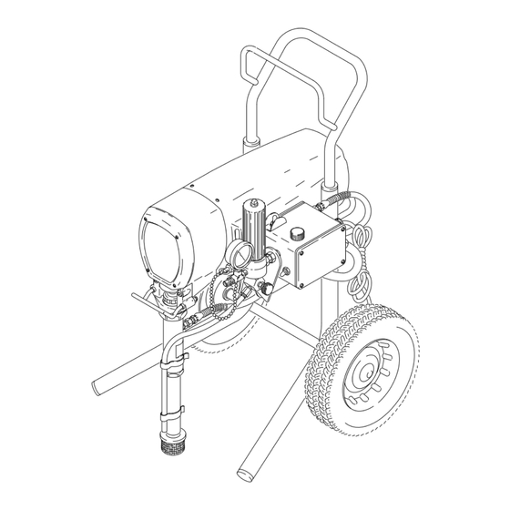
Page 5: Major Components
Major Components Fig. 1 Motor (Under shield shown) DC motor, 120 Vac, 12A, 1 phase Pressure Adjusting Knob Controls fluid outlet pressure ON/OFF Switch, Circuit Power switch that controls 120 Vac power to sprayer; with circuit breaker Breaker Drive Assembly Transfers power from DC motor to the displacement pump Fluid Filter Filter of fluid between source and spray gun... -
Page 6: Setup
WARNING 3. Fill the packing nut/wet–cup (216)1/3 full with Graco Throat Seal Liquid (TSL), supplied. If you supply your own hoses and spray gun, be sure the hoses are electrically conductive, that the 4. -
Page 7: Operation
Operation 7. To prime the pump, hold a metal part of the gun WARNING firmly against into a metal waste container. See Fig. 4 . Squeeze the trigger and hold it open, turn INJECTION HAZARD the ON/OFF switch to ON, and slowly increase the To reduce the risk of serious injury, pressure setting until the sprayer starts. - Page 8 Operation Cleaning a Clogged Tip Shutdown and Care 1. Check the packing nut/wet–cup daily. Relieve the pressure. Keep the packing nut/wet–cup 1/3 WARNING full with TSL at all times to help prevent fluid buil- dup on the piston rod and premature wear of pack- INJECTION HAZARD ings.
-
Page 9: Flushing
Flushing When to Flush 1. New Sprayer. The sprayer was factory tested in lightweight oil which was left in to protect pump parts. Before using water–base paint , flush with mineral spirits, then warm, soapy water, and then clean water. Before using oil–base paint, flush with mineral spir- its. -
Page 10: Troubleshooting
Troubleshooting Pressure Relief Procedure part of the gun firmly to a grounded metal pail. To reduce the risk of serious injury, including fluid injec- Trigger the gun to relieve pressure. tion, injury from splashing fluid or solvent in the eyes or 5. - Page 11 Troubleshooting TYPE OF PROBLEM WHAT TO CHECK WHAT TO DO If check is OK, go to next check When check is not OK refer to this column Motor runs and pump strokes, Check extension cord size and length. Replace cord with a larger size, grounding type extension cord.
-
Page 12: Motor Brush Replacement
Motor Brush Replacement NOTE: Replace the brushes when they have worn to 9. Test the brushes. Remove the connecting rod pin less than 10 mm. See Fig. 10. Always replace both (20). See Fig. 13, page 13. With the sprayer off, brushes at the same time. -
Page 13: Removing And Installing Pump
Fill the wet–cup/pack- Removal See Fig. 12. ing nut 1/3 full with Graco TSL. 1. Flush the pump, if possible, and relieve pressure again. Stop the pump with the piston rod in its low- est position, if possible. -
Page 14: Displacement Pump Repair
Displacement Pump Repair 6. Remove the sleeve. Use the sleeve removal tool, WARNING part no. 220–991, if necessary. To use the tool: screw the large nut (E) of the tool INJECTION HAZARD into the top of the cylinder (219). Screw down the To reduce the risk of serious injury, rod (D) to push the sleeve out. - Page 15 Displacement Pump Repair 11. Coat the piston rod and packings with oil. Carefully Lips of V–packings must face UP slide the assembly into the top of the sleeve (218). Lips of V–packings must face DOWN 12. Slide the sleeve/piston rod assembly (A) into the Leather packings bottom of the cylinder (219).
-
Page 16: Pressure Control
108,22 Fig. 21 Pressure Control WARNING INJECTION HAZARD 1. Follow the Pressure Relief Procedure. To reduce the risk of serious injury, 2. Disconnect the main hose (47). whenever you are instructed to relieve 3. Disconnect the drain tube (101) from the pump pressure, follow the Pressure Relief (39) and suction tube. -
Page 17: Motor Replacement
Motor Replacement 7. Use a plastic mallet to tap the displacement pump WARNING (39) from the rear to loosen the drive housing (18) from the motor bell (F). Pull off the drive housing. INJECTION HAZARD NOTE: To avoid damage to the drive housing: Do not To reduce the risk of serious injury, drop the gear cluster (9), which may stay engaged in the whenever you are instructed to relieve... -
Page 18: Bearing Housing And Connecting Rod
Bearing Housing and Connecting Rod NOTE: Stop the sprayer at the bottom of its stroke to WARNING get the crank (H) in its lowest position.To lower the crank manually, rotate the blades of the motor fan with INJECTION HAZARD a screwdriver. To reduce the risk of serious injury, whenever you are instructed to relieve 1. -
Page 19: Drive Housing Replacement
Drive Housing Replacement 6. Remove the screws (30 and 21) from the motor WARNING bell (F). INJECTION HAZARD 7. Tap the drive housing (18) with a plastic mallet to To reduce the risk of serious injury, loosen it from the motor bell, then pull it straight off. whenever you are instructed to relieve NOTE: To avoid damage to the drive housing: pressure, follow the Pressure Relief... -
Page 20: Sprayer Parts Drawing
Sprayer Parts Drawing 9 18a 3,98 Ref 61 Ref 6 Label 109, 116 Not visible Inside cover Outside cover Ref 43 110,111... -
Page 21: Sprayer Parts List
Sprayer Parts List Model 231–321, Series A Includes items 1–115 NOTE: Items 25, 55, 78, 79, and 96 are shown on page 22. Ref. Part No. Description Part No. Description Qty. 235–726 MOTOR KIT 48 214–570 FLUID FILTER 290–058 LABEL, identification, motor cover see manual 307–273 for parts 290–059 LABEL, identification, motor cover... -
Page 22: Hose And Gun Parts Drawing And List
Hose and Gun Parts Drawing and List Part No. Description 222–667 SPRAY GUN see manual 307–614 for parts 220–422 TIP GUARD, RAC IV see manual 307–848 214–701 HOSE, grounded, nylon; 3/16” ID; cpld 1/4 npsm(f); 3 ft. (9 m); spring guards both ends 223–541 HOSE, grounded, nylon;... -
Page 23: Accessories
Accessories Use Only Genuine Graco Parts and Accessories 55 Gallon (200 Liter) Suction Tube Kit 208–259 DANGER LABELS Includes: The English language DANGER label shown on page 1 is also on your sprayer. If you have paint- Part No. Description ers who do not read English, order one of the fol- 156–589... -
Page 24: Technical Data
Graco distributor to the original purchaser for use. As purchaser’s sole remedy for breach of this warranty, Graco will, for a period of twelve months from the date of sale, repair or replace any part of the Ultra equipment proven...
Need help?
Do you have a question about the ULTRA Plus+ 1500 and is the answer not in the manual?
Questions and answers