Table of Contents
Advertisement
Quick Links
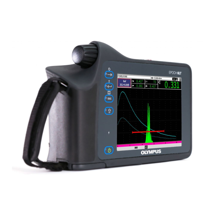
EPOCH 6LT
Ultrasonic Flaw Detector
User Interface Guide
This instruction manual contains essential information on how to use this Olympus product safely and effectively.
Before using this product, thoroughly review this instruction manual. Use the product as instructed.
Keep this instruction manual in a safe, accessible location.
DMTA-10084-01EN — Rev. 2
November 2018
Advertisement
Chapters
Table of Contents

Related Manuals for Olympus EPOCH 6LT


Summary of Contents for Olympus EPOCH 6LT
- Page 1 DMTA-10084-01EN — Rev. 2 November 2018 This instruction manual contains essential information on how to use this Olympus product safely and effectively. Before using this product, thoroughly review this instruction manual. Use the product as instructed. Keep this instruction manual in a safe, accessible location.
- Page 2 Olympus Scientific Solutions Americas, 48 Woerd Avenue, Waltham, MA 02453, USA Copyright © 2017, 2018 by Olympus. All rights reserved. No part of this publication may be reproduced, translated, or distributed without the express written permission of Olympus. This document was prepared with particular attention to usage to ensure the accuracy of the information contained therein, and corresponds to the version of the product manufactured prior to the date appearing on the title page.
-
Page 3: Table Of Contents
DMTA-10084-01EN, Rev. 2, November 2018 Table of Contents List of Abbreviations ..................ix Important Information — Please Read Before Use ........1 Intended Use .......................... 1 Instruction Manual ........................ 1 Safety Symbols ........................2 Safety Signal Words ....................... 2 Note Signal Words ......................... 3 Warranty Information ...................... - Page 4 DMTA-10084-01EN, Rev. 2, November 2018 Setup Menu ........................ 17 3.1.1 Setup Menu Icons ................... 18 3.1.2 Navigating Dialog Boxes and Setup Pages ..........19 4. Inspection Mode ..................23 Sidebar Menu ......................24 4.1.1 Sidebar Menu Button Actions ..............24 4.1.2 Adjustable Value Buttons ................
- Page 5 DMTA-10084-01EN, Rev. 2, November 2018 6.2.2 Damping ......................64 6.2.3 Pulser Type ...................... 64 6.2.4 Pulser Frequency .................... 65 6.2.5 Test Modes ...................... 65 6.2.6 Pulse Repetition Frequency (PRF) ............... 66 Adjusting the Receiver ..................... 67 6.3.1 Digital Receiver Filters .................. 68 6.3.2 Waveform Rectification .................
- Page 6 DMTA-10084-01EN, Rev. 2, November 2018 9.4.1 Create ......................105 9.4.2 File ........................107 9.4.3 Manage ......................117 9.4.4 Memo ......................122 9.4.5 Backup|Restore .................... 127 Grid View ......................... 130 9.5.1 Activating the Grid View ................130 9.5.2 Configuring the Grid ................... 131 9.5.3 Using the Grid ....................
- Page 7 DMTA-10084-01EN, Rev. 2, November 2018 11.6.1 Enabling the BEA Option ................187 11.6.2 Operating the BEA ..................188 11.7 Corrosion Module ....................189 11.7.1 Key Features ....................190 11.7.2 Corrosion Module Modes ................191 11.7.3 Corrosion Module Activation and Setup ..........194 List of Figures ....................
- Page 8 DMTA-10084-01EN, Rev. 2, November 2018 viii Table of Contents...
-
Page 9: List Of Abbreviations
DMTA-10084-01EN, Rev. 2, November 2018 List of Abbreviations automatic gain control ASME American Society of Mechanical Engineers abstand verstärkung größe American Welding Society back wall echo attenuator curved surface correction distance-amplitude correction distance gain size full-screen height Japanese Industrial Standard memory ultrasonic nondestructive testing overshoot... - Page 10 DMTA-10084-01EN, Rev. 2, November 2018 List of Abbreviations...
-
Page 11: Important Information - Please Read Before Use
The EPOCH 6LT is designed to perform nondestructive inspections on industrial and commercial materials. WARNING Do not use the EPOCH 6LT for any purpose other than its intended use. It must never be used to inspect or examine human or animal body parts. Instruction Manual This instruction manual contains essential information on how to use this Olympus product safely and effectively. -
Page 12: Safety Symbols
DMTA-10084-01EN, Rev. 2, November 2018 Safety Symbols The following safety symbols might appear on the instrument and in the instruction manual: General warning symbol This symbol is used to alert the user to potential hazards. All safety messages that follow this symbol shall be obeyed to avoid possible harm or material damage. Shock hazard caution symbol This symbol is used to alert the user to potential electric shock hazards. -
Page 13: Note Signal Words
Warranty Information Olympus guarantees your Olympus product to be free from defects in materials and workmanship for a specific period, and in accordance with conditions specified in the Olympus Scientific Solutions Americas Inc. -
Page 14: Technical Support
Retain packing materials, waybills, and other shipping documentation needed in order to file a damage claim. After notifying the carrier, contact Olympus for assistance with the damage claim and equipment replacement, if necessary. -
Page 15: Introduction
DMTA-10084-01EN, Rev. 2, November 2018 Introduction The EPOCH 6LT is a portable ultrasonic nondestructive testing (NDT) instrument designed primarily for inspections requiring high portability, such as rope access, and detection of flaw conditions in welds, pipes, turbine blades, and other structural and industrial materials. - Page 16 DMTA-10084-01EN, Rev. 2, November 2018 Introduction...
-
Page 17: Hardware User Interface Overview
DMTA-10084-01EN, Rev. 2, November 2018 1. Hardware User Interface Overview The EPOCH 6LT hardware keys and adjustment knob are used to control the software user interface. The hardware keys are located on the front panel of the instrument. The adjustment knob is located on the left side of the instrument (see Figure 1-1 on page 7). -
Page 18: Shift Key
DMTA-10084-01EN, Rev. 2, November 2018 Shift Key The Shift key ( ) is used to activate the second function, changing the way the ESC, Enter, and Tab keys function. ESC Key The ESC key ( ) is used to move the focus to the previous menu in the user interface (UI). -
Page 19: Adjustment Knob
DMTA-10084-01EN, Rev. 2, November 2018 Adjustment Knob The adjustment knob increases or decreases the value of the highlighted adjustable parameter (see Figure 1-2 on page 9). The Shift ( ), Enter ( ) key sequence switches the adjustment knob between coarse and fine adjustment of the highlighted parameter. - Page 20 DMTA-10084-01EN, Rev. 2, November 2018 Chapter 1...
-
Page 21: Software User Interface Overview
DMTA-10084-01EN, Rev. 2, November 2018 2. Software User Interface Overview The EPOCH 6LT live A-scan display is shown in Figure 2-1 on page 11. File name File ID number Flags Measurement Gain reading boxes adjustment Live A-scan view Gate 2 (blue) -
Page 22: File Identifier Bar
DMTA-10084-01EN, Rev. 2, November 2018 File Identifier Bar The file identifier bar appears at the top of the live A-scan display and shows the name and the ID number of the currently opened file (see Figure 2-2 on page 12). The file identifier bar also displays status flags. -
Page 23: Message Bar
DMTA-10084-01EN, Rev. 2, November 2018 Message Bar The message bar at the bottom of the screen displays certain messages and notifications in response to your actions (see example in Figure 2-4 on page 13). Figure 2-4 Message bar with a message example The message bar also displays a flag or flags that indicate when particular functions are active. -
Page 24: Modes
Figure 2-6 Example of an A-scan waveform with gates Modes The EPOCH 6LT software operates in two modes: setup mode and inspection mode. Each mode has a main menu. The menu in setup mode is called the setup menu. The menu in inspection mode is called the sidebar menu. -
Page 25: Figure 2-7 Setup Menu (Left) And Sidebar Menu (Right)
DMTA-10084-01EN, Rev. 2, November 2018 Figure 2-7 Setup menu (left) and sidebar menu (right) A set of shortcut menus are also available while in inspection mode. The shortcut menus offer quick access to specific parameters (see Figure 2-8 on page 15). For details on shortcut menus, see “Shortcut Menus”... - Page 26 DMTA-10084-01EN, Rev. 2, November 2018 Chapter 2...
-
Page 27: Setup Mode
DMTA-10084-01EN, Rev. 2, November 2018 3. Setup Mode The EPOCH 6LT Setup mode enables you to set up the instrument before an inspection or change setup parameters during an inspection. Setup Menu The setup menu presents dialog boxes and setup pages that contain parameters relevant to instrument setup. -
Page 28: Setup Menu Icons
DMTA-10084-01EN, Rev. 2, November 2018 To display the Setup menu When on the live A-scan display, press Shift ( ), and then Escape ( 3.1.1 Setup Menu Icons A setup menu icon opens a dialog box or submenu of icons (see Table 1 on page 18). Table 1 Setup menu icon actions Icon Description... -
Page 29: Navigating Dialog Boxes And Setup
DMTA-10084-01EN, Rev. 2, November 2018 cannot access the file identifier shortcut menu or measurement reading shortcut menu (see “Shortcut Menus” on page 28). • A setup page occupies the entire screen and an inspection is suspended until the setup page is dismissed. Figure 3-2 Dialog box (left) and setup page (right) To scroll through the setup menu icons ... -
Page 30: Figure 3-3 Setup Page As Initially Displayed
DMTA-10084-01EN, Rev. 2, November 2018 First parameter First parameter description value not highlighted highlighted Figure 3-3 Setup page as initially displayed To highlight (and select) the first parameter value on a dialog box or setup page On the dialog box or setup page, press Enter ( ) to highlight and select the first parameter value. - Page 31 DMTA-10084-01EN, Rev. 2, November 2018 Press the Shift ( ), Tab ( ) key sequence to return to the live A-scan. Setup Mode...
- Page 32 DMTA-10084-01EN, Rev. 2, November 2018 Chapter 3...
-
Page 33: Inspection Mode
DMTA-10084-01EN, Rev. 2, November 2018 4. Inspection Mode The EPOCH 6LT Inspection mode provides you full access to all of the inspection mode features, including a full-screen view of the live A-scan. The inspection mode menus include the sidebar menu (see Figure 4-1 on page 23) and the shortcut menus. -
Page 34: Sidebar Menu
DMTA-10084-01EN, Rev. 2, November 2018 Sidebar Menu The sidebar menu contains a set of buttons that immediately affect an ongoing inspection (see Figure 4-1 on page 23). NOTE You can change the persistence of the sidebar (pullout) menu in the Display setup page. -
Page 35: Adjustable Value Buttons
DMTA-10084-01EN, Rev. 2, November 2018 Table 2 Button types (continued) Type Example Description Menu open Button that opens a submenu of adjustable parameters and/or function buttons. The pointer ( ) identifies a submenu button. 4.1.2 Adjustable Value Buttons Both the sidebar menu and submenus can have one or more buttons with an adjustable value. -
Page 36: Using The Sidebar Menu And Submenus
DMTA-10084-01EN, Rev. 2, November 2018 The default behavior for the sidebar menu or sidebar submenu is that the first button is highlighted, but not selected, when you open the menu or submenu for the first time. If that button is an adjustable value button it must selected before it can be adjusted. - Page 37 DMTA-10084-01EN, Rev. 2, November 2018 — If the button opens a submenu, that submenu is opened (see “Using Sidebar Submenus” on page 27). Repeat the first three steps of this procedure until you are finished making changes. Press the Shift ( ), Tab ( ) key sequence to dismiss the Sidebar menu.
-
Page 38: Shortcut Menus
DMTA-10084-01EN, Rev. 2, November 2018 Shortcut Menus Shortcut menus are available while in Inspection mode. Shortcut menus offer you quick access to the following: • Setup pages in the data logger • Measurement and display setup • Gain adjustment box configuration 4.2.1 File Identifier Shortcut Menu The file identifier shortcut menu contains buttons that open data logger setup pages... -
Page 39: Measurement Reading Shortcut Menu
DMTA-10084-01EN, Rev. 2, November 2018 To use the file identifier shortcut menu While on the live A-scan screen, press Tab ( ) to highlight the file identifier bar, outlining it in red (see Figure 4-5 on page 29). Figure 4-5 Highlighted file identifier bar Press Enter ( ) to open the shortcut menu. -
Page 40: Figure 4-6 Measurement Reading Shortcut Menu
DMTA-10084-01EN, Rev. 2, November 2018 Figure 4-6 Measurement reading shortcut menu To use the measurement reading shortcut menu While on the live A-scan display, press Tab ( ) to highlight the measurement reading bar, outlining it in red (see Figure 4-7 on page 30). Figure 4-7 Highlighted measurement reading bar Press Enter ( ) to open the shortcut menu. -
Page 41: Gain Adjustment Shortcut Menu
DMTA-10084-01EN, Rev. 2, November 2018 For detailed information on the Display and Measurement setup pages, see “Display Setup Page” on page 41 and “Measurement Setup Page” on page 44. 4.2.3 Gain Adjustment Shortcut Menu The gain adjustment shortcut menu contains buttons that enable you to set the reference and scanning gain values (see Figure 4-8 on page 31). - Page 42 DMTA-10084-01EN, Rev. 2, November 2018 Press the Enter key ( ) to open the shortcut menu. For detailed information on making gain adjustments using the shortcut menu, see “Adjusting the Gain (System Sensitivity)” on page 59. Chapter 4...
-
Page 43: Setup
DMTA-10084-01EN, Rev. 2, November 2018 5. Setup Pages The EPOCH 6LT software includes a number of setup pages for adjusting instrument features and parameters. An example setup page is shown in Figure 5-1 on page 33. Title bar Currently selected parameter... -
Page 44: Opening A Setup Page
DMTA-10084-01EN, Rev. 2, November 2018 Figure 5-2 Settings menu Opening a Setup Page Opening a setup page requires opening and navigating through the setup menu, the Settings menu, and then opening one of the Settings menu setup pages. To open a setup page On the live A-scan screen, press the Shift ( ), Escape ( ) key sequence... -
Page 45: Using The Virtual Keypad
DMTA-10084-01EN, Rev. 2, November 2018 Press Enter ( ) to open the selected setup page. When you open a setup page, the first parameter description is highlighted, but the parameter value is not highlighted. You must highlight the first parameter value before you can change it. -
Page 46: Figure 5-3 Edit Page With Virtual Keypad
DMTA-10084-01EN, Rev. 2, November 2018 Figure 5-3 Edit page with virtual keypad To enter an alphanumeric value using the virtual keypad Press Tab ( ) to select the box that you want to edit, and then press Enter On the virtual keypad: a) Turn the adjustment knob to move to and highlight the character to be added. -
Page 47: File Management
See “Data Logger Setup Pages” on page 104. Instrument Settings Pages The Instrument Settings setup pages are used to set up the general hardware aspects of the EPOCH 6LT. 5.4.1 User Keys Setup Page Custom user keys affect the Inspection mode sidebar menu action that occurs when... -
Page 48: Figure 5-4 Default Home Screen (Live A-Scan)
DMTA-10084-01EN, Rev. 2, November 2018 Figure 5-4 Default home screen (live A-scan) You can change the action of the Shift, Tab key sequence in the User Keys and Home Keys setup page (see Figure 5-5 on page 39). Chapter 5... -
Page 49: Figure 5-5 Custom User Key Setup Page
DMTA-10084-01EN, Rev. 2, November 2018 Figure 5-5 Custom User Key setup page For example, if the G1Start parameter is selected, the result of pressing the Shift, Tab key sequence is that the Gate1 Sidebar submenu is displayed with the G1Start button selected (see Figure 5-6 on page 40). -
Page 50: Figure 5-6 G1Start Selected As Home Location
DMTA-10084-01EN, Rev. 2, November 2018 Figure 5-6 G1Start selected as Home location To change the Home location Open the User Keys and Home Keys setup page (see Figure 5-5 on page 39). Press the Tab key to select the dialog box containing the following parameters: —... -
Page 51: Display Setup Page
DMTA-10084-01EN, Rev. 2, November 2018 5.4.2 Display Setup Page The Display setup page enables you to set parameters that control aspects of the display. To open the Display setup page Select the Display Setup icon ( ) to open the Display setup page (see Figure 5-7 on page 41). - Page 52 DMTA-10084-01EN, Rev. 2, November 2018 • X-Axis Grid Mode (see Figure 5-8 on page 43) Sets the horizontal x-axis grid display mode — Off: no grid — Standard: 10 divisions spaced evenly and labeled 1 to 10 — Soundpath: five divisions spaced evenly and labeled with corresponding sound path values —...
-
Page 53: Figure 5-8 X-Axis Grid Mode Options
DMTA-10084-01EN, Rev. 2, November 2018 Standard grid: traditional flaw detector view with 10 divisions equally spaced across the screen range, and the numbers 1–10 appearing below each division. SoundPath grid: actual sound path measurements at equally spaced increments along the horizontal axis. This mode displays 5 divisions, each labeled with its corresponding sound path value (depending on the Basic >... -
Page 54: Measurement Setup Page
DMTA-10084-01EN, Rev. 2, November 2018 — Off — On • Brightness Used to adjust the screen brightness by choosing one of the preset values (0 %, 25 %, 50 %, 75 %, or 100 %). • Color Scheme Sets the overall instrument color scheme. —... -
Page 55: Figure 5-9 Measurement Setup Page
DMTA-10084-01EN, Rev. 2, November 2018 Information displayed in the measurement reading boxes Figure 5-9 Measurement Setup page The available parameter selections are: • Reading Selection Sets the measurement reading box mode. — Auto: Automatically makes the selection based on instrument function —... -
Page 56: Figure 5-10 Example Of Measurement Reading Boxes With Icons
DMTA-10084-01EN, Rev. 2, November 2018 NOTE The flags that appear in the upper-right corner of the display indicate units (see Units on page 49 and “Flags” on page 207), gate measurement modes (see “Gate Measurement Modes” on page 75 and “Flags” on page 207), and battery status (see “Flags”... - Page 57 DMTA-10084-01EN, Rev. 2, November 2018 Table 3 Available measurement readings (continued) Flag Measurement reading Description Gate 1 Surface Distance Horizontal distance to reflector in gate 1. Used with the Angle setting. Gate 2 Surface Distance Horizontal distance to reflector in gate 2. Used with the Angle setting.
- Page 58 DMTA-10084-01EN, Rev. 2, November 2018 Table 3 Available measurement readings (continued) Flag Measurement reading Description Gate 1 Minimum Amplitude Minimum amplitude in gate 1. Resets on gate adjustment and on most pulser/receiver adjustments. Gate 2 Minimum Amplitude Minimum amplitude in gate 2. Resets on gate adjustment and on most pulser/receiver adjustments.
- Page 59 DMTA-10084-01EN, Rev. 2, November 2018 Table 3 Available measurement readings (continued) Flag Measurement reading Description Gate1 Ref dB-Current Amp Comparison value in dB measuring the difference between the gate 1 echo height and the reference gain. Gate2 Ref dB-Current Amp Comparison value in dB measuring the difference between the gate 2 echo height and the reference gain.
-
Page 60: Instrument Setup Page
DMTA-10084-01EN, Rev. 2, November 2018 5.4.4 Instrument Setup Page The Instrument Setup page, shown in Figure 5-11 on page 50, enables you to configure general parameters such as the user interface language and the instrument date mode. To open the Instrument Setup page ... - Page 61 DMTA-10084-01EN, Rev. 2, November 2018 • Filter Group Selects receiver filter group. • Key Beep Sounds an audible tone on every key press. • Alarm Beep Activates an audible tone when a gate alarm is triggered. • Calibration Lock Locks access to all functions affecting calibration/waveform data. These include Basic, Pulser, Rcvr (receiver), and Trig settings, as well as Gain, Range, and Delay.
-
Page 62: Software Options Setup Page
DMTA-10084-01EN, Rev. 2, November 2018 5.4.5 Software Options Setup Page Use the Software Options page to enter an activation code for access to a software option not included with the standard instrument features. See “Defining Licensed and Unlicensed Software Features” on page 151 for details on software option activation. -
Page 63: Resets Setup Page
DMTA-10084-01EN, Rev. 2, November 2018 The available parameter selections are as follows: — Year Sets the year. — Month Sets the month. — Day Sets the day of the month. — Mode Sets the hour display mode (12 Hour or 24 Hour). —... -
Page 64: Wi-Fi Networks Setup Page
DMTA-10084-01EN, Rev. 2, November 2018 Figure 5-13 Resets setup page 5.4.8 Wi-Fi Networks Setup Page This page is used to configure a wireless LAN connection. See “Wi-Fi Networks” on page 145 for details on using the Wi-Fi Networks setup page. Instrument Info Setup Pages These pages primarily provide information about the state of the instrument. -
Page 65: Upgrade Setup Page
) to open the About setup page. 5.5.2 Upgrade Setup Page This page is used to upgrade the EPOCH 6LT system software. You can upgrade via a wireless LAN network, a USB flash drive, or a USB connection to a computer. To upgrade the system software... -
Page 66: Regulatory Setup Page
DMTA-10084-01EN, Rev. 2, November 2018 Figure 5-14 Upgrade setup page 5.5.3 Regulatory Setup Page This page displays regulatory information and labels. To open the Regulatory setup page Select the Regulatory icon ( ) to open the Regulatory setup page. 5.5.4 License Setup Page This page displays all the licensing information. -
Page 67: Legal Setup Page
DMTA-10084-01EN, Rev. 2, November 2018 5.5.5 Legal Setup Page This page displays patent information. To open the Legal setup page Select the Legal icon ( ) to open the Legal setup page. 5.5.6 Diagnostic Test Setup Page This page displays a list of diagnostic tests, and available test options. The Start button at the bottom of the page begins the test. -
Page 68: Figure 5-15 Diagnostic Test Setup Page
DMTA-10084-01EN, Rev. 2, November 2018 Figure 5-15 Diagnostic Test setup page Chapter 5... -
Page 69: Pulser/Receiver Adjustments
DMTA-10084-01EN, Rev. 2, November 2018 6. Pulser/Receiver Adjustments This chapter describes how to adjust the EPOCH 6LT pulser/receiver. Adjusting the Gain (System Sensitivity) To adjust the gain On the live A-scan screen, press the Tab key to select the Gain adjustment box (see Figure 6-1 on page 59). -
Page 70: Using The Auto Xx% Feature
DMTA-10084-01EN, Rev. 2, November 2018 6.1.1 Using the Auto XX% Feature The Auto XX% feature is used to quickly adjust the instrument gain (dB) setting to bring the gated peak echo to XX % FSH (full-screen height). Auto XX% is especially useful for bringing the echo from a reference indication to XX % FSH to establish the instrument’s reference gain level (see “Setting Reference Gain and Scanning Gain”... - Page 71 DMTA-10084-01EN, Rev. 2, November 2018 The gain display reads: Ref XX.X + 0.0 dB. Scanning gain can now be added or subtracted. Turn the adjustment knob to adjust the scanning gain. Press the Enter key to display the scanning gain buttons (see Figure 6-2 on page 62).
-
Page 72: Selecting And Adjusting The Pulser
Selecting and Adjusting the Pulser The pulser settings in the EPOCH 6LT are available in the Pulser dialog box. To select the pulser In the setup menu, turn the adjustment knob to navigate to the Pulser ( ). -
Page 73: Energy (Voltage)
6.2.1 Energy (Voltage) The EPOCH 6LT can adjust the pulse energy from 0 V to 400 V in increments of 100 V. You can set the pulse energy to a minimum to extend the battery life, or set very high pulse energy for the most difficult materials. -
Page 74: Damping
Selecting the correct damping setting fine-tunes the EPOCH 6LT in order to operate with a particular transducer selection. Depending on the transducer, the various damping settings either improve near-surface resolution or improve the instrument’s... -
Page 75: Pulser Frequency
DMTA-10084-01EN, Rev. 2, November 2018 NOTE The EPOCH 6LT uses PerfectSquare technology to achieve optimum response from the tunable square wave pulser. The PerfectSquare technology maximizes the energy used to drive the connected transducer while providing excellent near-surface resolution. To adjust the pulser waveform ... -
Page 76: Pulse Repetition Frequency (Prf)
6.2.6 Pulse Repetition Frequency (PRF) The EPOCH 6LT allows you to manually adjust the PRF from 10 Hz to 2000 Hz in 50 Hz (coarse) or 10 Hz (fine) increments. The instrument has an Auto-PRF mode to automatically adjust the PRF based on screen range. -
Page 77: Adjusting The Receiver
The EPOCH 6LT is a single-shot instrument. This means that the instrument acquires, measures, and draws the complete A-scan with each pulse rather than using multiple acquisitions to construct a full waveform. The measurement rate in the EPOCH 6LT is always equal to the PRF rate unless you are using a multiplexer. -
Page 78: Digital Receiver Filters
6.3.1 Digital Receiver Filters The EPOCH 6LT has a total instrument bandwidth of 0.2–26.5 MHz at −3 dB. The instrument offers 8 standard fixed digital filters designed to improve the signal-to-noise ratio by filtering out unwanted high and/or low frequency noise. -
Page 79: Waveform Rectification
6.3.2 Waveform Rectification The EPOCH 6LT can operate in one of four different rectification modes: Full, Half+, Half-, or RF (unrectified). NOTE RF mode is not active while operating in special software feature modes, such as DAC mode or Peak Memory. -
Page 80: Figure 6-5 Horizontal Line Indicating The Reject Level
DMTA-10084-01EN, Rev. 2, November 2018 NOTE Reject can also be used in the unrectified RF mode. To adjust the reject level In the receiver dialog box, press the Tab key to select Reject, and then turn the adjustment knob to change the setting. The reject level is displayed as a blue horizontal line on the instrument display (see Figure 6-5 on page 70) or two lines in the case of the Rect = RF mode. -
Page 81: Gates
DMTA-10084-01EN, Rev. 2, November 2018 7. Gates This chapter describes how to use the standard gates of the EPOCH 6LT ultrasonic flaw detector. Activating the Gates To activate the gates On the setup menu, turn the adjustment knob to select the Gate1 icon (... -
Page 82: Measurement Gates 1 And 2
Figure 7-1 Gate (G1) status On Measurement Gates 1 and 2 The EPOCH 6LT has two standard independent gates. In the A-scan, a gate is represented by a horizontal line with fixed start and end points. The length and horizontal position of the gate identifies the sound path range, while the vertical position of the gate line represents a threshold amplitude level for echoes of interest. -
Page 83: Quickly Adjusting Basic Gate Parameters
DMTA-10084-01EN, Rev. 2, November 2018 Gate 1 (red) Gate 2 (blue) Figure 7-2 Gate 1 and gate 2 (with echo-to-echo turned on) Both gates can be used to do the following: • Measure thickness with straight-beam transducers • Measure sound path and depth with angle beam transducers •... -
Page 84: Figure 7-3 Gate 1 Submenu
DMTA-10084-01EN, Rev. 2, November 2018 NOTE Before you can access a gate menu, the gate must be activated. (see “Activating the Gates” on page 71). Figure 7-3 Gate 1 submenu The available gate parameters are as follows: Start Used to adjust the gate start position. Width Used to adjust the gate width. -
Page 85: Gate Measurement Modes
(see “Zooming in on a Gate” on page 81 for details). Gate Measurement Modes The EPOCH 6LT ultrasonic flaw detector’s two gates provide measurements of a gated indication based on one of four possible measurements modes. You can select the measurement mode of a gate in the Gate1 or Gate2 dialog box (see Figure 7-4 on page 75). -
Page 86: Figure 7-5 Gate Trigger Indicator In Edge (Left) And Peak (Right) Modes
DMTA-10084-01EN, Rev. 2, November 2018 When a measurement is in progress using one of the measurement gates, a small triangle appears on the gate to indicate from which echo/point the measurement is being acquired (see Figure 7-5 on page 76 and Figure 7-6 on page 77). This triangle is called the gate trigger indicator. -
Page 87: Figure 7-6 Gate Trigger Indicator In 1Stpeak (Left) And J-Flank (Right) Modes
DMTA-10084-01EN, Rev. 2, November 2018 1stPeak Acquires measurement readings based on the position of the first peak to break the threshold of the gate within the gated region (see Figure 7-6 on page 77). J-Flank Acquires thickness measurement readings based on the position of the first crossing point of a gated signal and amplitude measurement readings from the highest peak of the first echo in the gated region (see Figure 7-6 on page 77). -
Page 88: Viewing Measurement Readings
NOTE The EPOCH 6LT does not acquire measurement readings unless the indication of interest is within a gated region of the screen. You should be careful to adjust the Start, Width, and Level of a measurement gate so that only the indication of interest falls within the gated region, as per the measurement mode definitions above. -
Page 89: Gate Tracking And Echo-To-Echo Measurements
DMTA-10084-01EN, Rev. 2, November 2018 Gate Tracking and Echo-to-Echo Measurements The gate tracking feature enables you to make echo-to-echo measurements whenever this feature is required by an application. Echo-to-echo measurements can be made between gate 2 and gate 1. Gate tracking maintains a constant separation between the position of the indication in the first gate and the start position of the second gate. -
Page 90: Time-Of-Flight Mode
Echo-to-echo flag Figure 7-7 Echo-to-echo measurement example Time-of-Flight Mode The EPOCH 6LT is capable of displaying time-of-flight (TOF) sound path data for a gated indication. Time-of-flight is the location of the reflector in terms of microseconds. The time-of-flight mode does not divide the measurement reading value by two. The entire time-of-flight through the test piece in both directions is displayed. -
Page 91: Zooming In On A Gate
Figure 7-8 Time-of-flight measurement Zooming in on a Gate The EPOCH 6LT can quickly zoom in the screen range to provide fine resolution of a particular inspection zone. When the zoom is activated, the instrument automatically brings the point that corresponds to the gate start to the left side of the screen and adjusts the displayed range to match the gate width. -
Page 92: Gate Alarms
In unrectified (RF) mode, gate alarms can be used in positive, negative, or dual gate modes. By default, when an alarm condition is triggered, the EPOCH 6LT emits an audible beep. The instrument also illuminates the red indicator, above the display window, corresponding to the gate with which the alarm has been triggered. -
Page 93: Minimum Depth Alarm
DMTA-10084-01EN, Rev. 2, November 2018 Positive Negative Figure 7-9 Gate tick marks indicating alarm threshold type To set a threshold alarm Activate the gate in the Gate1 or Gate2 dialog box (see “Navigating Dialog Boxes and Setup Pages” on page 19 for details on using the dialog boxes). Use the G(1 or 2) Start, Width, or Level parameters to position the gate to cover the desired area. -
Page 94: Figure 7-10 Minimum Depth Alarm Marker
DMTA-10084-01EN, Rev. 2, November 2018 Minimum depth alarm marker Figure 7-10 Minimum depth alarm marker To set a minimum depth alarm Activate the gate in the Gate1 or Gate2 dialog box (see “Navigating Dialog Boxes and Setup Pages” on page 19 for details on using the dialog boxes. Use the G(1 or 2) Start, Width, or Level parameters to position the gate to cover the desired area. -
Page 95: 7.10 Peak Memory
DMTA-10084-01EN, Rev. 2, November 2018 To set up a minimum depth alarm with gate tracking With the G1 Alarm set to Min Depth, press the Tab key to move to G1 Min Depth, and then adjust the setting. 7.10 Peak Memory The peak memory function enables on-screen capture and storage in memory of the amplitude of each A-scan acquisition. -
Page 96: 7.11 Peak Hold
DMTA-10084-01EN, Rev. 2, November 2018 NOTE You cannot activate the peak memory function in the unrectified Rect = RF mode. To activate the peak memory function With a gate active and the sidebar menu displayed, turn the adjustment knob to select the PeakMem button (see Figure 7-11 on page 85). -
Page 97: 7.12 Freeze
7.12 Freeze The freeze function holds, or freezes, the information on the screen at the moment it is activated, and the EPOCH 6LT pulser/receiver becomes inactive. No further data is acquired. A freeze ( ) flag appears, indicating that the function is active. - Page 98 DMTA-10084-01EN, Rev. 2, November 2018 To deactivate the freeze function On the sidebar menu, select and activate Freeze to deactivate a manual or automatic freeze. Chapter 7...
-
Page 99: Calibration
DMTA-10084-01EN, Rev. 2, November 2018 8. Calibration Calibrating the EPOCH 6LT is the process of adjusting the unit so that it measures accurately on a particular material, using a particular transducer at a particular temperature. In calibrating the instrument, you set the zero offset and velocity parameters. The zero offset (sometimes referred to as probe delay) is set to compensate for the dead time between the firing of the main pulse and the entry of the sound into the test piece. - Page 100 DMTA-10084-01EN, Rev. 2, November 2018 On the setup menu, select the UT icon ( ), and then press the Enter key to open the UT dialog box (see Figure 8-1 on page 91). Press the Enter key to select Range, and then turn the adjustment knob to set the range based on the sound path range within the selected calibration block.
-
Page 101: Figure 8-1 Ut Dialog Box
DMTA-10084-01EN, Rev. 2, November 2018 Figure 8-1 UT dialog box If you are using an angle beam transducer, select the Angle icon ( ), and then press the Enter key to open the angle dialog box (see Figure 8-2 on page 92): a) Select Angle, and then use the adjustment knob to set the correct refracted angle for the probe (0 for a straight beam probe, 45 for a 45°... -
Page 102: Calibration Modes
Straight Beam Modes Straight beam calibrations can be performed using one of two modes. For the purposes of the EPOCH 6LT calibration, straight beam refers to all zero-degree probes, including contact, dual, delay line, immersion, etc. The two straight beam calibration modes are as follows: •... -
Page 103: Angle Beam Modes
For accurate measurements, you must first verify the refracted angle of the transducer, since the EPOCH 6LT calculates depth values based on sound path and known refracted angle. The shallow reflector depth allows for zero offset calibration, and the deep reflector depth allows for velocity calibration. - Page 104 NOTE If the EPOCH 6LT is set to work in metric units, the calibration process is exactly the same, except the entries are in millimeters rather than inches. To calibrate using a straight beam transducer Couple the transducer to the 0.200 in.
-
Page 105: Figure 8-3 Calibration - Dialog Box Initial Setup
DMTA-10084-01EN, Rev. 2, November 2018 Figure 8-3 Calibration — Dialog box initial setup Adjust G1Start until the gate is over the first back wall echo. Press the Tab key to highlight the Gain adjustment box, and then complete the Auto 80% procedure (see Figure 8-4 on page 96). See “Using the Auto XX% Feature”... -
Page 106: Figure 8-4 Calibration - Ready To Auto 80% On Thin Echo
DMTA-10084-01EN, Rev. 2, November 2018 Figure 8-4 Calibration — Ready to Auto 80% on thin echo Press the Tab key to highlight the Collect button, and then press the Enter key to capture the thin echo (see Figure 8-6 on page 98). Chapter 8... -
Page 107: Figure 8-5 Calibration - Ready To Collect Thin Echo
DMTA-10084-01EN, Rev. 2, November 2018 Figure 8-5 Calibration — Ready to collect thin echo 10. Couple the transducer to the 0.400 in. step of the calibration test block. 11. Repeat the Auto 80% procedure for this step of the calibration test block. 12. -
Page 108: Figure 8-6 Calibration - Ready To Collect Thick Echo
DMTA-10084-01EN, Rev. 2, November 2018 Figure 8-6 Calibration — Ready to collect thick echo 13. Press the Enter key to capture the thick echo. When the calibration is complete, the following message is briefly displayed at the bottom of the calibration dialog box: SUCCESS! Then the calibration dialog box is replaced by the setup menu. -
Page 109: Figure 8-7 Calibration - Successfully Completed
DMTA-10084-01EN, Rev. 2, November 2018 Figure 8-7 Calibration — Successfully completed Calibration... - Page 110 DMTA-10084-01EN, Rev. 2, November 2018 Chapter 8...
-
Page 111: Data Logger
DMTA-10084-01EN, Rev. 2, November 2018 9. Data Logger Olympus has designed the data logger for ease of use, with a wide range of features. The data logger serves two basic purposes: • To manage test and setup data • To display certain data in a graphical format, as a screen snapshot, or as full- motion video. -
Page 112: Data File Types
Setup Pages” on page 19 for instructions on using the setup pages. Data File Types EPOCH 6LT ultrasonic flaw detectors enable you to create several types of files based on application requirements. There are two standard file types, calibration and incremental, and one advanced file type, 2D. -
Page 113: Calibration File Type
Saving Data to Active Files The EPOCH 6LT allows you to save data whenever there is an active file open with an active ID. If there is no active ID and you try to save the data, the instrument displays the error message “No active ID”... -
Page 114: Data Logger Setup
DMTA-10084-01EN, Rev. 2, November 2018 — Alarm conditions — Gate measurement modes — Sound path leg for each gate — Up to five measurement reading box values (all active user-selected measurements on the instrument screen) — A-scan waveform — Peak memory envelope or peak hold waveform, if active —... -
Page 115: Create
Create The Create setup page is used to create files (a default file: NONAME00, is created by the EPOCH 6LT). Files can be created on the instrument or in the GageView Pro software and transferred to the instrument. Each time you save file data, it is linked to a file identifier (ID). The number of IDs in a file depends on the file type selected and the number of data sets that you have saved. -
Page 116: Figure 9-3 File Name Edit
DMTA-10084-01EN, Rev. 2, November 2018 In the Create setup page, press the Enter key to select the file type value, and then turn the adjustment knob to choose INC or CAL. Press the Tab key to highlight the Filename box. Enter characters (up to 32) using the virtual keypad, adjustment knob, and Enter key (see Figure 9-3 on page 106). -
Page 117: File
DMTA-10084-01EN, Rev. 2, November 2018 b) Enter a Start ID for the INC file. If the File Type is CAL, press the Tab key, and then enter a calibration ID. After you have completed the file setup, press the Tab key to highlight the Create button. -
Page 118: Figure 9-4 File Setup Page
Selecting a File as the Active Storage Location The EPOCH 6LT maintains a list of all files on the instrument. To save information to a file, you must first select that file and then set it as the active storage location. -
Page 119: Figure 9-5 Name And Id Of Open File On The Live A-Scan Display
DMTA-10084-01EN, Rev. 2, November 2018 When you select Save on the sidebar menu, on-screen data and settings are saved to the currently opened file ID. Figure 9-5 Name and ID of open file on the live A-scan display 9.4.2.2 Viewing File Contents After you have saved data to a file, you can view the saved setup and waveform data. -
Page 120: Figure 9-6 Saved File Waveform
DMTA-10084-01EN, Rev. 2, November 2018 Figure 9-6 Saved file waveform Press the Tab key to select the Setup button. Press the Enter key to view the complete setup parameters for the current ID (see Figure 9-7 on page 111). Chapter 9... -
Page 121: Figure 9-7 Saved File Data
DMTA-10084-01EN, Rev. 2, November 2018 Figure 9-7 Saved file data To switch to a different file ID NOTE Calibration (CAL) files only contain a single ID. Press the Enter key to highlight the ID value. Turn the adjustment knob to scroll through the saved IDs in the file. As you scroll to the next ID, the corresponding information is displayed. -
Page 122: Figure 9-8 Viewing All The Ids In A File
DMTA-10084-01EN, Rev. 2, November 2018 To choose from a large number of IDs NOTE Calibration (CAL) files only contain a single ID. While on the setup parameters page (see Figure 9-7 on page 111), press the Tab key to highlight the Select ID button, and then press the Enter key to open the Select ID setup page (see Figure 9-8 on page 112). -
Page 123: Figure 9-9 Saved File Waveform And Data
DMTA-10084-01EN, Rev. 2, November 2018 To take a snap shot of the waveform With the waveform data page displayed, turn the adjustment knob to highlight the Snap Shot button (see Figure 9-9 on page 113). Press the Enter key to save the snap shot to the cloud or a USB flash drive as a bitmap (.bmp) image file. -
Page 124: Figure 9-10 Recalled File Data
DMTA-10084-01EN, Rev. 2, November 2018 NOTE Calibration (CAL) files only contain a single ID. To recall a file ID from the Contents page With the Contents setup page displayed, turn the adjustment knob to highlight the Recall button. Press the Enter key to bring the saved data to the live A-scan display (see Figure 9-10 on page 114). - Page 125 DMTA-10084-01EN, Rev. 2, November 2018 To recall a file ID from the File setup page In the File setup page, turn the adjustment knob, and then press the Enter key to select the file that you want to recall. Press the Tab key to select the Contents button. Press the Enter key to view the file contents.
-
Page 126: Figure 9-11 Details Setup Page
DMTA-10084-01EN, Rev. 2, November 2018 Figure 9-11 Details setup page 9.4.2.6 Viewing a Summary of All Saved Data After you have completed saving data to a file, you may want to view a summary of the different measurements saved in the different IDs within the file. To view a summary of all saved data in a file In the File setup page, turn the adjustment knob, and then press the Enter key to select the file that you want to view. -
Page 127: Manage
DMTA-10084-01EN, Rev. 2, November 2018 Figure 9-12 Summary setup page 9.4.3 Manage The Manage setup page can accomplish the following tasks in files (see Figure 9-13 on page 118): • Edit • Copy • Delete • Clear • Select ID To select a file in the Manage setup page ... -
Page 128: Figure 9-13 Manage Setup Page
DMTA-10084-01EN, Rev. 2, November 2018 Figure 9-13 Manage setup page 9.4.3.1 Edit The Edit button is used to edit information within saved files. To edit file information In the Manage page, turn the adjustment knob to highlight a file. Press the Tab key to select the Edit button. Press the Enter key to view the file contents (see Figure 9-14 on page 119). -
Page 129: Figure 9-14 Edit Setup Page
DMTA-10084-01EN, Rev. 2, November 2018 Figure 9-14 Edit setup page 9.4.3.2 Copy The Copy button is used to make a duplicate copy of a file saved on the instrument. To copy a file In the Manage page, turn the adjustment knob to highlight a file. Press the Tab key to select the Copy button. -
Page 130: Figure 9-15 Copy Setup Page
DMTA-10084-01EN, Rev. 2, November 2018 Figure 9-15 Copy setup page 9.4.3.3 Delete The Delete button is used to delete a saved file from the instrument. The file name and all the saved data and IDs contained within it are deleted. To delete a file Press the Tab key to select the Delete button. -
Page 131: Figure 9-16 Delete Dialog Box
DMTA-10084-01EN, Rev. 2, November 2018 Figure 9-16 Delete dialog box 9.4.3.4 Clear The Clear button is used to delete all of the data from a saved file, but it does not delete the file from the instrument. To clear a file of data Press the Tab key to select the Clear button. -
Page 132: Memo
DMTA-10084-01EN, Rev. 2, November 2018 To select an ID within a file In the Manage page, turn the adjustment knob to highlight a file. Press the Tab key to highlight the Select ID button, and then press the Enter key to select the highlighted file and open the Select ID setup page. -
Page 133: Figure 9-19 Memo Setup Page
DMTA-10084-01EN, Rev. 2, November 2018 particular data file, open that file before creating the memo. To place a memo in the file with a specific reading, enter the memo before saving the reading. To place a memo in the file after saving an ID, enter the memo after that ID is saved. To add a memo On the Settings menu, select the Memo icon and open the Memo setup page. -
Page 134: Figure 9-20 Memo Dictionary Page
DMTA-10084-01EN, Rev. 2, November 2018 Press the Enter key to open the Dictionary setup page. Press the Tab key to select Custom, then turn the adjustment knob to select one of the custom labels (see Figure 9-20 on page 124). Press the Tab key to select the Insert button Figure 9-20 Memo Dictionary page Press the Enter key to insert the custom label into the memo and return to the... -
Page 135: Figure 9-21 Memo Dictionary Page - Editing A Label
DMTA-10084-01EN, Rev. 2, November 2018 Figure 9-21 Memo Dictionary page — Editing a label Press the Tab key to move down to the Update button, and then press the Enter key. To associate more custom label information In the Memo page, press the Tab key to highlight Memo, and then press the Enter key. -
Page 136: Figure 9-22 Memo Dictionary Page - Inserting Label Info
DMTA-10084-01EN, Rev. 2, November 2018 First empty space Figure 9-22 Memo Dictionary page — Inserting label info Press the Tab key to highlight Dictionary, and then press the Enter key. Press the Tab key to select Custom, and then turn the adjustment knob to select one of the custom labels. -
Page 137: Backup|Restore
DMTA-10084-01EN, Rev. 2, November 2018 Figure 9-23 Memo Dictionary page — Inserted info Press the Tab key to highlight Update, and press the Enter key. When you are finished creating your memo. press the Tab key to highlight Save, then press Enter to return to the Settings menu. To erase all the editable text in the Memo setup page In the Memo setup page, press the Tab key to highlight Clear. -
Page 138: Figure 9-24 Backup|Restore Setup Page
DMTA-10084-01EN, Rev. 2, November 2018 The Backup|Restore setup page enables you to do the following: • Copy language support files to or from a USB flash drive • Copy DGS/AVG custom probe files to or from a USB flash drive •... - Page 139 DMTA-10084-01EN, Rev. 2, November 2018 — Copy language BIN file to USB mass storage Exports current language file from the internal memory to the USB flash drive. — Copy XML Schema File from USB mass storage Imports an XML Schema file from the USB flash drive to the internal memory to support file exports in the XML format.
-
Page 140: Grid View
DMTA-10084-01EN, Rev. 2, November 2018 IMPORTANT Restore permanently overwrites all existing data on the EPOCH 6LT with data from a USB flash drive. Grid View Using the grid view enables you to observe the measurements saved in multiple IDs of the active file displayed on the live A-scan display. This feature can be used for any file or file type, but it is most often used when conducting a thickness survey using a predefined inspection pattern. -
Page 141: Configuring The Grid
DMTA-10084-01EN, Rev. 2, November 2018 Figure 9-25 Grid dialog box 9.5.2 Configuring the Grid Use the grid dialog box to configure the grid display options. • Grid Size Controls the amount of the live A-scan display dedicated to displaying the grid. Half Size splits the live display area. -
Page 142: Using The Grid
DMTA-10084-01EN, Rev. 2, November 2018 All measurements above this value are colored green. All measurements between the Low Range Thickness value and the High Range Thickness value are colored yellow. To configure the grid size and color In the grid dialog box, press the Tab key to highlight the Grid Size box. Turn the adjustment knob to select Half Size or Full Size. -
Page 143: Figure 9-26 Grid View On The Live A-Scan Display
DMTA-10084-01EN, Rev. 2, November 2018 Figure 9-26 Grid view on the live A-scan display To use the arrow buttons Press the Tab key to move the selection from one arrow button to the next. On the selected arrow button, press the Enter key to execute the desired function as described below. - Page 144 DMTA-10084-01EN, Rev. 2, November 2018 — The Up Arrow ( ) button moves the selection to the cell above the currently selected cell and changes the active file ID to that of the newly selected cell. — The Down Arrow ( ) button moves the selection to the cell below the currently selected cell and changes the active file ID that of to the newly selected cell.
-
Page 145: Video Recorder
However, components of the video recording system are found in the sidebar menu in addition to the setup menu. 9.6.1 Activating the Video Recorder Before activating the video recorder, set up the EPOCH 6LT to display the events you want to record. Data Logger... -
Page 146: Recording And Saving Video
DMTA-10084-01EN, Rev. 2, November 2018 To activate the video recorder In the setup menu, turn the adjustment knob to highlight the Tools icon ( and then press Enter to open the Tools submenu. Turn the adjustment knob to highlight the Video icon ( Press the Enter key to open the Video dialog box, and then press the Enter key again to highlight the Video parameter. -
Page 147: Figure 9-29 Recording In Progress
DMTA-10084-01EN, Rev. 2, November 2018 To record video NOTE While recording a live video, gate and gain adjustments are available. No other parameters can be adjusted during live recording. Activate the video recorder (see “To activate the video recorder” on page 136). Press the Enter key to begin recording. -
Page 148: Figure 9-30 Create Video File Setup Page
DMTA-10084-01EN, Rev. 2, November 2018 — To finish recording and save the video to a file, select Save (see “To save a recording” on page 138 for details). — To erase the current video, select Clear. To flag (or mark) a point in the video, select the Flag button, and then press the Enter key. -
Page 149: Working With Video Files
The data logger enables you to do the following: • Review video recorded of the live A-scan display. • Export video files via USB or the cloud. • Import video files from other EPOCH 6LT ultrasonic flaw detectors. Figure 9-31 Video Files setup page Data Logger... -
Page 150: Figure 9-32 Video Review Setup Page
DMTA-10084-01EN, Rev. 2, November 2018 To open the Video settings Select the Video icon ( ) in the Settings menu to open the Video Files setup page. See “Navigating Dialog Boxes and Setup Pages” on page 19 for instructions on using the setup pages. - Page 151 DMTA-10084-01EN, Rev. 2, November 2018 — Pause pauses video playback. — Resume continues the video playback from the pause point. — << Frame or Frame>> moves back or forward one frame at time. — << Flag or Flag>> moves back or forward to the previous or next flag in the video (see “To record video”...
-
Page 152: Figure 9-33 Import (Video File) Setup Page
DMTA-10084-01EN, Rev. 2, November 2018 NOTE The HOST connector accommodates either a USB flash drive or a wireless LAN (Wi-Fi) adaptor. The instrument will import a file through or from the device connected to the HOST connector. In the Video Files setup page, select the Import button. Press the Enter key to open the Import setup page. - Page 153 DMTA-10084-01EN, Rev. 2, November 2018 To delete a video file In the Video Files setup page, turn the adjustment knob to select a file. Press the Tab key to highlight the Delete button. Press the Enter key to delete the selected file. Data Logger...
- Page 154 DMTA-10084-01EN, Rev. 2, November 2018 Chapter 9...
-
Page 155: 10. Wi-Fi Networks
DMTA-10084-01EN, Rev. 2, November 2018 10. Wi-Fi Networks The wireless LAN (Wi-Fi) setup pages are used to set up the instrument to connect to a wireless LAN (Wi-Fi) network through a wireless LAN adaptor. NOTE You can connect to the cloud through Wi-Fi. See your network administrator about configuring your instrument to connect to the cloud. -
Page 156: Figure 10-1 Wi-Fi Networks Setup Page
DMTA-10084-01EN, Rev. 2, November 2018 a) Press the Tab key to select the Enable parameter. b) Turn the adjustment knob to set the Enable parameter to On. Press the Tab key to move to the list of available networks. Turn the adjustment knob to select a network, and then press the Enter key to confirm your selection. -
Page 157: Figure 10-2 Wi-Fi Secure Logon Page
DMTA-10084-01EN, Rev. 2, November 2018 Figure 10-2 Wi-Fi secure logon page After the network connection is made, a page displays to show the status, strength, security, and IP address of the connection (see Figure 10-4 on page 149). b) If the network you select does not require a password, press the Enter key to connect to the selected network (see Figure 10-3 on page 148). -
Page 158: Figure 10-3 Wi-Fi Unsecured Logon Page
DMTA-10084-01EN, Rev. 2, November 2018 Figure 10-3 Wi-Fi unsecured logon page A page displays to show the status, strength, security, and IP address of the connection (see Figure 10-4 on page 149). Chapter 10... -
Page 159: 10.2 Adding A Wireless Lan (Wi-Fi) Network
DMTA-10084-01EN, Rev. 2, November 2018 Figure 10-4 Wi-Fi connection status page 10.2 Adding a Wireless LAN (Wi-Fi) Network If a wireless LAN (Wi-Fi) network that you want to connect to is not listed in the networks list on the Wi-Fi Networks setup page. You can manually enter the necessary information to connect to that network. -
Page 160: Figure 10-5 Add Network Setup Page
DMTA-10084-01EN, Rev. 2, November 2018 Other parameters may be displayed on the page, depending on the security type. Enter a password, and then press the Tab key to select the Connect button. Press the Enter key to connect to the newly added network. If there is a problem connecting to the added network, the following message is displayed in the message bar: “Error on Network Setting.”... -
Page 161: 11. Software Features And Options
If an optional software feature is not activated, you cannot access that feature in the Software Options dialog box (see “Activating Software Options” on page 152). Olympus can provide you with an activation code that grants access to the option so you do not have to return the instrument to a service center. -
Page 162: 11.2 Activating Software Options
DMTA-10084-01EN, Rev. 2, November 2018 11.2 Activating Software Options Software options are activated in the Software Options setup page. To activate a software option On the setup menu, select the Settings icon ( ), and then press the Enter key to open the Settings submenu. -
Page 163: 11.3 Dynamic Dac/Tcg
Similarly, reflectors that are smaller than those used to create the curve fall below the level, while larger reflectors exceed the curve level. When a DAC curve is created in the EPOCH 6LT ultrasonic flaw detector, the instrument also creates a time-corrected gain (TCG) setup. TCG is used to compensate for the same factors as DAC, but the presentation is different. -
Page 164: Enabling The Dac/Tcg Feature
DMTA-10084-01EN, Rev. 2, November 2018 The EPOCH 6LT DAC/TCG feature allows you to quickly and easily toggle between DAC and TCG views, giving you the freedom to use both techniques during a single inspection. When you switch from DAC view to TCG view, the DAC curves are displayed as TCG lines across the screen. -
Page 165: Applying Reference Correction
DMTA-10084-01EN, Rev. 2, November 2018 The available active modes are: Standard (see “Building a DAC Curve in Standard or ASME III Mode” on page 156), ASME-3 (see “Building a DAC Curve in Standard or ASME III Mode” on page 156), JIS (see “JIS DAC” on page 169), and Custom (see “Custom DAC Curves”... -
Page 166: Building A Dac Curve In Standard Or Asme Iii Mode
DMTA-10084-01EN, Rev. 2, November 2018 Figure 11-2 DAC/TCG dialog box 11.3.3 Building a DAC Curve in Standard or ASME III Mode Building a DAC curve in Standard or ASME III mode involves the same series of steps, but the modes produce different visual results: •... -
Page 167: Figure 11-3 Dac/Tcg Sidebar Submenu
DMTA-10084-01EN, Rev. 2, November 2018 The DAC/TCG submenu should be displayed (see Figure 11-3 on page 157). If it is not displayed, do the following: a) Press the Tab key to display the sidebar menu. b) Press the Tab key to highlight the DAC/TCG button, and then press the Enter key to open the DAC/TCG submenu. -
Page 168: Figure 11-4 First Dac Point
DMTA-10084-01EN, Rev. 2, November 2018 Figure 11-4 First DAC point Turn the adjustment knob to move the gate trigger indicator to the next echo. Press the Tab key to highlight AUTO 80%, and then press the Enter key to bring the second echo to 80 % full-screen height. -
Page 169: Figure 11-5 Second Dac Point
DMTA-10084-01EN, Rev. 2, November 2018 Figure 11-5 Second DAC point Turn the adjustment knob to move the gate trigger indicator to the next echo. Press the Tab key to highlight AUTO 80%, and then press the Enter key to bring the selected point to 80 % full-screen height. -
Page 170: Figure 11-6 Completed Dac Curve
DMTA-10084-01EN, Rev. 2, November 2018 Figure 11-6 Completed DAC curve 10. Select the Done button to end curve acquisition and switch to DAC inspection mode. In Figure 11-7 on page 161, the instrument has drawn a DAC curve with three levels from the first point to the second.The AUTO 80% function has brought the second point to 80 % full-screen height. -
Page 171: Figure 11-7 Partial Dac Curve With Each Echo Set To 80 % Fsh
DMTA-10084-01EN, Rev. 2, November 2018 Figure 11-7 Partial DAC curve with each echo set to 80 % FSH 11.3.3.1 Other Adjustments for Building a DAC Curve You can increase the instrument range or increase the display delay to increase the number of echoes that you can see. -
Page 172: Dac Inspection Mode
DMTA-10084-01EN, Rev. 2, November 2018 Adjust the Angle, Thick, X Value, and CSC parameters as desired. Figure 11-8 Completed DAC curve 11.3.4 DAC Inspection Mode When the DAC curve is complete and the instrument is in inspection mode, the DAC/TCG submenu displays a new set of parameters: G1Start The start position of gate 1 can be adjusted on the DAC/TCG submenu or the Gate1 submenu. -
Page 173: Figure 11-9 Completed Dac Curves In Tcg View Mode
DMTA-10084-01EN, Rev. 2, November 2018 View This parameter enables you to toggle between the DAC curve acquired and the corresponding TCG setup based on the DAC curve information (see Figure 11-9 on page 163). Figure 11-9 Completed DAC curves in TCG view mode Next DAC This parameter cycles through the available DAC curves (if more than one is available) for amplitude comparison with on-screen echoes. -
Page 174: Gain Adjustment Options
DMTA-10084-01EN, Rev. 2, November 2018 Save This parameter saves the DAC curve to internal memory. Auto XX% This parameter allows you to return to DAC acquisition mode, providing access to the Add, Delete, Erase, and Done functions. (Edit is not available in the TCG view.) While DAC/TCG is active, you have full control of the Range, Delay, and Zoom settings. -
Page 175: Figure 11-11 Standard Dac With 6 Db Scanning Gain
To quickly find and identify potential defects, it is commonly required by code to increase the gain (scanning gain) on the EPOCH 6LT from the reference (calibration) gain for scanning purposes. However, after a potential defect is identified, this gain is usually removed to view the reflector at Ref gain level, set at calibration. -
Page 176: Figure 11-12 Standard Dac With Scanning Gain Off
DMTA-10084-01EN, Rev. 2, November 2018 Select the Off button to turn the scanning gain off completely. Figure 11-12 on page 166 shows a Standard DAC setup with 6 dB of scanning gain added. Figure 11-12 Standard DAC with scanning gain off When reference correction is active, the digital comparison between a captured reflector and the DAC curve is accurate even with the scanning gain applied to the inspection, provided that the gated echo is not saturated. -
Page 177: Figure 11-13 Dac With 6 Db Scan Gain - Reference Correction Active
A-scan and the DAC curve to continue the inspection. This is accomplished on the EPOCH 6LT using the curve gain (DAC curve-adjustment gain). To adjust the curve gain In the DAC/TCG submenu, press the Tab key to select Gain Step. -
Page 178: Figure 11-14 Dac Curves With Adjusted Gain
The coupling conditions on the test surface can often cause signal loss after calibrating a DAC curve, which results in inaccurate comparisons of the test reflectors with the calibrated DAC curve. The EPOCH 6LT can be easily adjusted for this potential difference by adding transfer correction to the calibrated base gain after completing the DAC curve setup. -
Page 179: Jis Dac
DMTA-10084-01EN, Rev. 2, November 2018 Turn the adjustment knob to highlight the Add button, and then press the Enter key to add the scanning gain to the base gain and to apply the transfer correction. 11.3.6 JIS DAC The Japanese Industrial Standard (JIS) DAC mode meets the requirements of JIS Z3060. -
Page 180: Custom Dac Curves
DMTA-10084-01EN, Rev. 2, November 2018 Adjust the G1 Start value and use the Add button to add points and build the desired DAC curve (see Figure 11-16 on page 170). Figure 11-16 JIS curves When the curve is complete, select Done, then press the Enter key. Use the adjustment knob to highlight Next DAC and press the Enter key to cycle through the available DAC curves. -
Page 181: Figure 11-17 Custom Dac Setup
DMTA-10084-01EN, Rev. 2, November 2018 To activate and set up the customized curves Activate the DAC/TCG feature (see “Enabling the DAC/TCG Feature” on page 154). In the DAC/TCG dialog box, turn the adjustment knob to set the DAC/TCG Mode to Custom. Set the Curve Type to either Curve or Straight (polynomial or straight-line segments). -
Page 182: 11.4 Dgs/Avg
DMTA-10084-01EN, Rev. 2, November 2018 Figure 11-18 Completed Custom DAC When the customized DAC curve points have been captured and completed, you have full capability to toggle between DAC and TCG views, to manipulate Range, Delay, CAL Zero, and Angle, and to add necessary scanning gain, curve gain adjustment or transfer correction. -
Page 183: Enabling The Dgs/Avg Option
If you want to use a probe that is not in the default library, you can enter the required transducer characteristics in the GageView Pro computer interface program and download them to the EPOCH 6LT. Probes that are downloaded to the instrument appear in the custom transducers section of the transducer library. -
Page 184: Figure 11-19 Dgs/Avg Dialog Box
DMTA-10084-01EN, Rev. 2, November 2018 Figure 11-19 DGS/AVG dialog box Press the Enter key to highlight the DGS/AVG parameter box. Turn the adjustment knob to set the DGS/AVG Mode to On. The DGS/AVG dialog box enables you to define the exact probe being used for the inspection, and to set up the DGS/AVG curve to be drawn. - Page 185 DMTA-10084-01EN, Rev. 2, November 2018 For angle beam probes, the available reflectors are as follows: ○ Side-drilled hole (SDH) ○ K1-IIW block arc ○ K2-DSC block ○ Flat-bottom hole (FBH) — Refl. Dia. Used for angle beam inspections only. This allows you to define the diameter of the flat-bottom hole (FBH) or side-drilled hole (SDH) used as a reference reflector.
-
Page 186: Figure 11-20 Reference Reflector Before Capture
DGS/AVG curve. Figure 11-20 Reference reflector before capture After capturing the reference reflector, the EPOCH 6LT automatically calculates the DGS/AVG curve(s) and displays them at the correct registration level amplitude on the screen (see Figure 11-21 on page 177). -
Page 187: Curve-Adjustment Options
Figure 11-21 DGS/AVG curves on the screen 11.4.2 Curve-Adjustment Options After a DGS/AVG curve has been calculated on the EPOCH 6LT, you can make adjustments to that curve during an inspection. These adjustments include gain adjustments allowing proper defect scanning and code-compliant defect sizing, as well as reference-reflector adjustments. -
Page 188: Dgs/Avg Curve Gain
20 % FSH. Therefore, to inspect beyond a certain depth/sound path time within a part, it is necessary to raise the gain of both the live A-scan and the DGS/AVG curve to continue the inspection. This is accomplished on the EPOCH 6LT using the DGS/AVG curve-adjustment gain. -
Page 189: Registration Level Adjustment
This is usually equal to the critical flaw size for the application. The EPOCH 6LT allows you to adjust this registration level during a live inspection. -
Page 190: Relative Attenuation Measurement
This allows the EPOCH 6LT to plot the attenuation curve (in steel) for a particular reflector size without having to acquire individual data points, as is required in a DAC/TCG setup. -
Page 191: 11.5 Aws D1.1/D1.5 Weld Rating Software
α = ∆ Vs / 2d * 1000 [dB/m] 11.5 AWS D1.1/D1.5 Weld Rating Software The AWS D1.1 software feature for the EPOCH 6LT has been created to assist you in performing inspections covered under the American Welding Society D1.1 (or D1.5) Structural Welding code for steel. -
Page 192: Enabling The Aws D1.1 Option
11.5.1 Enabling the AWS D1.1 Option The first step in operating the EPOCH 6LT for AWS D1.1 inspections is to calibrate the instrument for the transducer and test conditions. For information on the angle beam calibration of the EPOCH 6LT, see “Calibration” on page 89, or follow the appropriate guidelines from the American Welding Society. -
Page 193: Figure 11-25 Active Aws With A Ref Level Of 50
Press the Tab key to highlight Ref Level, and then set the level to what you desire (default value is 50 %) The EPOCH 6LT enables you to define the reference level to adhere to best practices and procedures. The reference reflector is often a side-drilled hole in the calibration block used for the angle beam calibration. -
Page 194: Figure 11-26 Aws Ref B Value Dialog Box
DMTA-10084-01EN, Rev. 2, November 2018 Press the Tab key to highlight Ref B, and then press Enter to set a Ref B value to begin the AWS inspection (see Figure 11-26 on page 184). 10. Press Enter again to store the Ref B value. The Ref B value represents the gain level necessary to bring the echo from a reference reflector to a user defined full-screen height (FSH). -
Page 195: Scanning Gain
DMTA-10084-01EN, Rev. 2, November 2018 Figure 11-27 Active AWS with D rating 11.5.2 Scanning Gain AWS codes require that you apply a certain amount of scanning gain to the Ref B gain value. This allows you to locate flaws that might be smaller or deeper in the test piece than the reference flaw. -
Page 196: Calculating A And C Values
11.5.3 Calculating A and C Values When a gated echo whose peak is below 100 % FSH is present, the EPOCH 6LT automatically calculates the A and C values necessary to provide a D indication rating value. For the A value, the EPOCH 6LT automatically calculates the required dB value to bring the gated echo to reference height. -
Page 197: Enabling The Bea Option
DMTA-10084-01EN, Rev. 2, November 2018 • The first is an inspection where potential defects may not be oriented parallel to the direction of sound from the transducer. Sound will still reflect from these defects, but the reflection may be directed away from the transducer. In this situation, little or no signal is returned to the instrument for direct measurement. -
Page 198: Operating The Bea
DMTA-10084-01EN, Rev. 2, November 2018 Figure 11-28 Activating the BEA 11.6.2 Operating the BEA The BEA option displays an independent back wall gain in the G2 BEA Gain parameter of the gate 2 dialog box. This control replaces the G2 Min Depth parameter while BEA is active. -
Page 199: 11.7 Corrosion Module
1. 11.7 Corrosion Module The EPOCH 6LT corrosion module provides a rapid and simple solution for flaw detector users to perform basic corrosion inspections. This feature simplifies instrument operation for corrosion applications, reduces set up time, and enables more efficient data collection. -
Page 200: Key Features
The EPOCH 6LT uses two pulsing channels to calculate the zero offset for each transducer element and delay line. -
Page 201: Corrosion Module Modes
Figure 11-30 Corrosion module grid view 11.7.2 Corrosion Module Modes The EPOCH 6LT ultrasonic flaw detector corrosion module uses two modes of operation: scanning (flaw detector, or FD) mode and precision (corrosion, or CRSN) mode. You can easily switch between measurement modes. When the corrosion module is active the current mode is indicated in the message bar, and some features are not available, including the Pulser, Angle, Sizing menus, and receiver filters. -
Page 202: Figure 11-31 Scanning Mode Screen
Scanning Mode Screen The EPOCH 6LT screen in scanning mode is similar to the standard flaw detector screen. The current mode and connected transducer are indicated in the message bar at the bottom of the screen (see Figure 11-31 on page 192). -
Page 203: Figure 11-32 Precision Mode Screen
(see “Grid View” on page 130). Precision Mode Screen The EPOCH 6LT screen in precision mode has a modified screen layout compared to the standard flaw detector screen. Some flaw detector functions are limited or unavailable when the instrument is in precision mode (see Figure 11-32 on page 193). -
Page 204: Corrosion Module Activation And Setup
To activate the Corrosion Module Connect an appropriate transducer to the EPOCH 6LT. If an Olympus thickness gage dual transducer is connected to the EPOCH 6LT, a dialog box will prompt you to press the Enter key to continue (see Figure 11-33 on page 194). -
Page 205: Figure 11-34 Corrosion Dialog Box
DMTA-10084-01EN, Rev. 2, November 2018 Select the Corrosn icon ( ) to open the Corrosion dialog box (see Figure 11-24 on page 182). See “Navigating Dialog Boxes and Setup Pages” on page 19 for details on using dialog boxes. Figure 11-34 Corrosion dialog box Press the Enter key to highlight the Corrosion parameter box. -
Page 206: Figure 11-35 Transducer Setup Page
You can improve upon the do-zero measurement accuracy by performing a straight beam thickness calibration while the corrosion module is active. For best results, Olympus recommends that you perform a separate calibration in both modes Chapter 11... - Page 207 DMTA-10084-01EN, Rev. 2, November 2018 (precision and scanning), as each mode uses a separate set of calibration data. Also, the calibration must be performed using an Olympus thickness gage dual transducer. See “Calibration” on page 89 for instructions on performing a thickness calibration.
-
Page 208: Figure 11-37 Incorrectly Triggered Measurement
DMTA-10084-01EN, Rev. 2, November 2018 Figure 11-37 Incorrectly triggered measurement To manually adjust the gain in precision mode In the precision corrosion mode sidebar menu, press the Tab key to select the ACG menu item. Turn the adjustment knob to set AGC to Off (see Figure 11-38 on page 199). Chapter 11... -
Page 209: Figure 11-38 Agc Off In Precision Mode
DMTA-10084-01EN, Rev. 2, November 2018 Figure 11-38 AGC Off in precision mode Select Gain and turn the adjustment knob to adjust the gain value (see Figure 11-39 on page 200). Software Features and Options... -
Page 210: Figure 11-39 Adjust Gain Value In Precision Mode
DMTA-10084-01EN, Rev. 2, November 2018 Figure 11-39 Adjust gain value in precision mode To control extended blanking (gate 1 start position) Select G1Start from the Sidebar menu and turn the adjustment knob to increase or decrease the gate 1 start position until the measurement is correctly triggered (see Figure 11-40 on page 201). -
Page 211: Figure 11-40 Correctly Triggered Measurement
DMTA-10084-01EN, Rev. 2, November 2018 Figure 11-40 Correctly triggered measurement 11.7.3.3 Echo-to-Echo Measurements The corrosion module echo-to-echo mode measures the distance between an echo in Gate 2 and an echo in Gate 1. Echo-to-echo measurements are most commonly used to determine the thickness of coated materials, since the first back wall measurement includes the thickness of the coating. -
Page 212: Figure 11-41 Corrosion Dialog Box
DMTA-10084-01EN, Rev. 2, November 2018 Figure 11-41 Corrosion dialog box In the receiver ( ) dialog box, set Rect to RF (see Figure 11-42 on page 203). The Rect setting enables you to view the positive and negative amplitude values. Chapter 11... -
Page 213: Figure 11-42 Receiver Dialog Box
DMTA-10084-01EN, Rev. 2, November 2018 Figure 11-42 Receiver dialog box Press ESC twice to dismiss the setup menu and view the echo-to-echo measurement in the live A-scan (see Figure 11-42 on page 203). Software Features and Options... -
Page 214: Figure 11-43 Echo-To-Echo Measurement
DMTA-10084-01EN, Rev. 2, November 2018 Figure 11-43 Echo-to-echo measurement Shear wave errors in echo-to-echo mode During a corrosion module inspection in echo-to-echo mode using a dual transducer, an unwanted shear wave often occurs because of the dual transducer roof angle. Shear wave velocity is slower than that of a longitudinal wave, so the shear component is displayed after the first back wall echo. -
Page 215: Figure 11-44 Shear Wave Measurement Error
DMTA-10084-01EN, Rev. 2, November 2018 Figure 11-44 Shear wave measurement error To adjust the measurement window start position On the Corrosion sidebar menu, highlight G2Start (see Figure 11-45 on page 206). Turn the adjustment knob to change the measurement window start position. Software Features and Options... -
Page 216: Figure 11-45 Corrosion Sidebar Menu (G2Start)
DMTA-10084-01EN, Rev. 2, November 2018 Figure 11-45 Corrosion sidebar menu (G2Start) Chapter 11... -
Page 217: Table 4 Flag Descriptions
DMTA-10084-01EN, Rev. 2, November 2018 Appendix: Flags Table 4 on page 207 provides a description of the possible flags. Table 4 Flag descriptions Flag Description Length units are inches. Length units are millimeters. Length units are microseconds. Indicates that the Shift (2 Function) key has been pressed. - Page 218 DMTA-10084-01EN, Rev. 2, November 2018 Table 4 Flag descriptions (continued) Flag Description Gate 1 is in first peak measurement mode. Gate 2 is in first peak measurement mode. Gate 1 is in J-Flank measurement mode. Gate 2 is in J-Flank measurement mode. DAC is active.
- Page 219 DMTA-10084-01EN, Rev. 2, November 2018 Table 4 Flag descriptions (continued) Flag Description Peak Hold reference echo is active. Indicates that a USB flash drive is installed. A wireless LAN (Wi-Fi) network is connected. Wireless LAN (Wi-Fi) network connection error. Indicates that video record mode is actively acquiring a video. Indicates that the gated signal occurs within Leg 1 during an angle beam inspection.
- Page 220 DMTA-10084-01EN, Rev. 2, November 2018 Appendix...
-
Page 221: List Of Figures
DMTA-10084-01EN, Rev. 2, November 2018 List of Figures Figure 1-1 EPOCH 6LT front panel ..................7 Figure 1-2 Adjustment knob ....................9 Figure 2-1 Live A-scan display elements ................11 Figure 2-2 File identifier bar with ID example ..............12 Figure 2-3 Measurement reading boxes example ............ - Page 222 DMTA-10084-01EN, Rev. 2, November 2018 Figure 5-9 Measurement Setup page ................. 45 Figure 5-10 Example of measurement reading boxes with icons ........46 Figure 5-11 Instrument Setup page ..................50 Figure 5-12 Clock setup page ....................52 Figure 5-13 Resets setup page ....................54 Figure 5-14 Upgrade setup page ..................
- Page 223 DMTA-10084-01EN, Rev. 2, November 2018 Figure 9-13 Manage setup page ..................118 Figure 9-14 Edit setup page ....................119 Figure 9-15 Copy setup page ....................120 Figure 9-16 Delete dialog box ..................... 121 Figure 9-17 Clear dialog box ....................121 Figure 9-18 Select ID setup page ..................
- Page 224 DMTA-10084-01EN, Rev. 2, November 2018 Figure 11-17 Custom DAC setup ..................171 Figure 11-18 Completed Custom DAC ................172 Figure 11-19 DGS/AVG dialog box ..................174 Figure 11-20 Reference reflector before capture ..............176 Figure 11-21 DGS/AVG curves on the screen ..............177 Figure 11-22 (Ref) Gain adjustment box ................
-
Page 225: List Of Tables
DMTA-10084-01EN, Rev. 2, November 2018 List of Tables Table 1 Setup menu icon actions ..................18 Table 2 Button types ......................24 Table 3 Available measurement readings ................ 46 Table 4 Flag descriptions ....................207 List of Tables... - Page 226 DMTA-10084-01EN, Rev. 2, November 2018 List of Tables...
-
Page 227: Index
DMTA-10084-01EN, Rev. 2, November 2018 Index about setup page 54 calibration activating basic setup 89 peak hold 86 modes 92 peak memory 86 angle beam 93 software options 152 straight beam 92 zoom 81 CAUTION signal word 3 adjusting clock setup page 52 damping 64 corrosion module filter 69... - Page 228 DMTA-10084-01EN, Rev. 2, November 2018 transfer correction 168 auto freeze 208 damping, adjustment 64 AWS 208 DANGER signal word 2 battery charging 209 data logger battery powered 209 file CSC 208 menu 122 DAC 208 types 102 DGS 208 grid view 130 E-E 208 activating 130 first peak 208...
- Page 229 8 battery performance 63 tab 8 indication in gate 78 minimum depth alarm availability 84 overwriting EPOCH 6LT data 130 icons 18 peak memory and RF mode 86 important information 1 PerfectSquare technology 65 IMPORTANT signal word 3...
- Page 230 DMTA-10084-01EN, Rev. 2, November 2018 energy, adjusting 63 sidebar submenus 25 signal words information notes 3 receiver adjustment 67 IMPORTANT 3 recorder, video 135 NOTE 3 reference gain 60 TIP 3 regulatory setup page 56 safety 2 reject function 70 CAUTION 3 reject function and RF mode, note 70 DANGER 2...
- Page 231 DMTA-10084-01EN, Rev. 2, November 2018 warnings, misuse of instrument 1 warranty information 3 video record 135 waveform rectification 69 activating 135 wireless LAN using 136 adaptor 145 viewing measurement readings 78 adding a network 149 connecting 145 WARNING signal word 2 networks setup page 54 warning symbols general 2...
- Page 232 DMTA-10084-01EN, Rev. 2, November 2018 Index...
Need help?
Do you have a question about the EPOCH 6LT and is the answer not in the manual?
Questions and answers